
"Manufacturer's Certification for Credit" Manual
Page 1
... Model Number(s) of Property Qualifying for Credit LiftMaster LA412 Solar Gate Operator System (Single Gate Model LA4121PKG) LiftMaster LA412 Solar Gate Operator System (Dual Gate Model LA412-2PKG) LiftMaster LA412 Solar Residential DC Linear Actuator (Single Gate Model LA4121PKGDC) LiftMaster LA412 Solar Residential DC Linear Actuator (Dual Gate Model LA412-2PKGDC) LiftMaster LA400 Residential DC Linear Actuator (Single Gate...
... Model Number(s) of Property Qualifying for Credit LiftMaster LA412 Solar Gate Operator System (Single Gate Model LA4121PKG) LiftMaster LA412 Solar Gate Operator System (Dual Gate Model LA412-2PKG) LiftMaster LA412 Solar Residential DC Linear Actuator (Single Gate Model LA4121PKGDC) LiftMaster LA412 Solar Residential DC Linear Actuator (Dual Gate Model LA412-2PKGDC) LiftMaster LA400 Residential DC Linear Actuator (Single Gate...

LiftMaster Gate Operator Feature Chart Manual
Page 1
...300 cycles per day 850 lbs. 100 cycles per day 850 lbs. 100 cycles per day (see specific product sell sheets at LiftMaster.com *Cycles noted are for specific details) 800 lbs. 120 cycles per day 1000 lbs. 250 cycles per day For more ... Alarm Dual Voltage Warranty Period LA500PKGU 24VDC Residential/ Light Commercial Linear Actuator 500 cycles RESIDENTIAL GATE OPERATORS LA400PKGU LA412PKGU RSL12U 24VDC Residential Linear Actuator 12VDC Solar Residential Linear Actuator 12VDC Residential/ Light Commercial Slide Gate Operator RSW12U 12VDC Residential Swing Gate Operator 400 cycles...
...300 cycles per day 850 lbs. 100 cycles per day 850 lbs. 100 cycles per day (see specific product sell sheets at LiftMaster.com *Cycles noted are for specific details) 800 lbs. 120 cycles per day 1000 lbs. 250 cycles per day For more ... Alarm Dual Voltage Warranty Period LA500PKGU 24VDC Residential/ Light Commercial Linear Actuator 500 cycles RESIDENTIAL GATE OPERATORS LA400PKGU LA412PKGU RSL12U 24VDC Residential Linear Actuator 12VDC Solar Residential Linear Actuator 12VDC Residential/ Light Commercial Slide Gate Operator RSW12U 12VDC Residential Swing Gate Operator 400 cycles...

LiftMaster Gate Operator Feature Chart Manual
Page 2
...-Tailgate Yes Yes Yes Yes Yes Yes Plug-in -Class Approx. 16 cycles Approx. 22 cycles Solar Performance* per day per hour © 2015 LiftMaster All Rights Reserved 845 Larch Ave., Elmhurst, IL 60126 LiftMaster.com LMGTCTOOOV 12/15 For more information about our best-in-class features, see specific product sell... sheets at LiftMaster.com Max. Selectable within Selectable within Phase Phase 7 years Res. 5 years Comm. 2 years 2 years 1/2 HP 50 ft. 1 HP 50 ft. 1/2 HP 45 ft. 1 HP ...
...-Tailgate Yes Yes Yes Yes Yes Yes Plug-in -Class Approx. 16 cycles Approx. 22 cycles Solar Performance* per day per hour © 2015 LiftMaster All Rights Reserved 845 Larch Ave., Elmhurst, IL 60126 LiftMaster.com LMGTCTOOOV 12/15 For more information about our best-in-class features, see specific product sell... sheets at LiftMaster.com Max. Selectable within Selectable within Phase Phase 7 years Res. 5 years Comm. 2 years 2 years 1/2 HP 50 ft. 1 HP 50 ft. 1/2 HP 45 ft. 1 HP ...

RSL12U Installation Manual
Page 2
...18 INSTALL THE COVER 20 ADJUSTMENT 21 LIMIT AND FORCE ADJUSTMENT 21 OBSTRUCTION TEST 22 PROGRAMMING 23 REMOTE CONTROLS (NOT PROVIDED 23 LIFTMASTER INTERNET GATEWAY (NOT PROVIDED 24 ERASE ALL CODES 24 ERASE LIMITS 24 TO REMOVE AND ERASE MONITORED ENTRAPMENT PROTECTION DEVICES 24 ...29 DRIVE CHAIN 29 TROUBLESHOOTING 30 DIAGNOSTIC CODES 30 CONTROL BOARD LEDS 33 TROUBLESHOOTING CHART 34 APPENDIX 36 DUAL GATE SETTINGS 36 SOLAR PANEL(S 37 LIMIT SETUP WITH A REMOTE CONTROL 41 WIRING DIAGRAM 42 REPAIR PARTS 43 ACCESSORIES 44 WARRANTY 46 SAFETY SAFETY SYMBOL...
...18 INSTALL THE COVER 20 ADJUSTMENT 21 LIMIT AND FORCE ADJUSTMENT 21 OBSTRUCTION TEST 22 PROGRAMMING 23 REMOTE CONTROLS (NOT PROVIDED 23 LIFTMASTER INTERNET GATEWAY (NOT PROVIDED 24 ERASE ALL CODES 24 ERASE LIMITS 24 TO REMOVE AND ERASE MONITORED ENTRAPMENT PROTECTION DEVICES 24 ...29 DRIVE CHAIN 29 TROUBLESHOOTING 30 DIAGNOSTIC CODES 30 CONTROL BOARD LEDS 33 TROUBLESHOOTING CHART 34 APPENDIX 36 DUAL GATE SETTINGS 36 SOLAR PANEL(S 37 LIMIT SETUP WITH A REMOTE CONTROL 41 WIRING DIAGRAM 42 REPAIR PARTS 43 ACCESSORIES 44 WARRANTY 46 SAFETY SAFETY SYMBOL...

RSL12U Installation Manual
Page 7
for use in vehicular slide gate applications: Usage Classification Main AC Supply System Operating Voltage Accessory Power Solar Power Max Maximum Gate Weight Maximum Gate Travel Distance Maximum Gate Travel Speed Maximum Daily Cycle Rate Maximum Duty Cycle Operating Temperature Expansion Board Inherent ...
for use in vehicular slide gate applications: Usage Classification Main AC Supply System Operating Voltage Accessory Power Solar Power Max Maximum Gate Weight Maximum Gate Travel Distance Maximum Gate Travel Speed Maximum Daily Cycle Rate Maximum Duty Cycle Operating Temperature Expansion Board Inherent ...

RSL12U Installation Manual
Page 16
... • ALL electrical connections MUST be performed until disconnecting the electrical power (AC or solar and battery) and locking-out the power via the operator power switch. SOLAR APPLICATIONS: For solar applications refer to Solar Panels section in the circuit by a qualified individual. • DO NOT install ANY ... or attempt to your application. 15 INSTALLATION STEP 5 EARTH GROUND ROD Use the proper earth ground rod for either 120 Vac or a solar panel (not provided). NOTE: The operator should cut the ground wire too short, break it, or destroy its integrity, replace it with...
... • ALL electrical connections MUST be performed until disconnecting the electrical power (AC or solar and battery) and locking-out the power via the operator power switch. SOLAR APPLICATIONS: For solar applications refer to Solar Panels section in the circuit by a qualified individual. • DO NOT install ANY ... or attempt to your application. 15 INSTALLATION STEP 5 EARTH GROUND ROD Use the proper earth ground rod for either 120 Vac or a solar panel (not provided). NOTE: The operator should cut the ground wire too short, break it, or destroy its integrity, replace it with...

RSL12U Installation Manual
Page 18
... control board. Plug in the transformer. 17 Red (+) Red (+) wire from new wire harness kit J15 Plug (new wire harness, Model K94-37236) (solar wires) Black (-) Black (-) wire from the control board. NOTE: You may see a small spark when plugging the J15 plug into the board. 6.... J15 plug labeled BATT on the control board by squeezing the plug and pulling it from the new J15 plug as shown. Red (+) J15 Plug (solar wires) Black (-) 7AH Battery To use a 33AH battery in the transformer. INSTALLATION STEP 6 continued... Unplug the transformer. 2. Plug in place of ...
... control board. Plug in the transformer. 17 Red (+) Red (+) wire from new wire harness kit J15 Plug (new wire harness, Model K94-37236) (solar wires) Black (-) Black (-) wire from the control board. NOTE: You may see a small spark when plugging the J15 plug into the board. 6.... J15 plug labeled BATT on the control board by squeezing the plug and pulling it from the new J15 plug as shown. Red (+) J15 Plug (solar wires) Black (-) 7AH Battery To use a 33AH battery in the transformer. INSTALLATION STEP 6 continued... Unplug the transformer. 2. Plug in place of ...

RSL12U Installation Manual
Page 29
... Department (main control board) Accessory Power Switched Com (-) Acc Power +12 Vdc Com (-) Acc Power +12 Vdc Accessory Power Unswitched NOTE: To conserve power for solar applications, the lock relay will only activate for four seconds near the close (maintained switch overrides external safeties and resets alarm condition within line-of...
... Department (main control board) Accessory Power Switched Com (-) Acc Power +12 Vdc Com (-) Acc Power +12 Vdc Accessory Power Unswitched NOTE: To conserve power for solar applications, the lock relay will only activate for four seconds near the close (maintained switch overrides external safeties and resets alarm condition within line-of...
RSL12U Installation Manual
Page 30
... at that while at the site voltage readings be taken at the fuse box BEFORE proceeding. Use only LiftMaster part 29-NP712 for proper operation Inspect all power (AC, solar, battery) to the operator before servicing. DRIVE CHAIN Over time, the drive chain on contact with 33AH... operator properly can be tightened. Have a qualified service person make repairs to gate hardware. • ALL maintenance MUST be performed by a LiftMaster professional. • Activate gate ONLY when it can increase the risk of INJURY or DEATH. • Use the manual disconnect release ONLY ...
... at that while at the site voltage readings be taken at the fuse box BEFORE proceeding. Use only LiftMaster part 29-NP712 for proper operation Inspect all power (AC, solar, battery) to the operator before servicing. DRIVE CHAIN Over time, the drive chain on contact with 33AH... operator properly can be tightened. Have a qualified service person make repairs to gate hardware. • ALL maintenance MUST be performed by a LiftMaster professional. • Activate gate ONLY when it can increase the risk of INJURY or DEATH. • Use the manual disconnect release ONLY ...

RSL12U Installation Manual
Page 31
... oldest code (up to the chart on the display. Release the STOP button. For continued protection against fire and electrocution: • DISCONNECT power (AC or solar and battery) BEFORE installing or servicing operator. OPEN, CLOSE, & STOP BUTTONS DIAGNOSTICS DISPLAY The operator will show "Er" then "CL" alternately for six seconds. Press...
... oldest code (up to the chart on the display. Release the STOP button. For continued protection against fire and electrocution: • DISCONNECT power (AC or solar and battery) BEFORE installing or servicing operator. OPEN, CLOSE, & STOP BUTTONS DIAGNOSTICS DISPLAY The operator will show "Er" then "CL" alternately for six seconds. Press...

RSL12U Installation Manual
Page 34
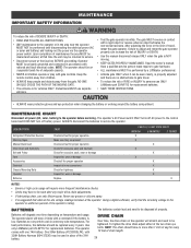
CONTROL BOARD LEDS TROUBLESHOOTING STATUS LEDS INPUT OFF POWER ON OFF state AC charger or Solar power available BATT OFF CHARGING ON Not charging Three stage battery charging TIMER OFF The timer is disabled ON The timer is enabled MEDIUM BLINK (1 ...
CONTROL BOARD LEDS TROUBLESHOOTING STATUS LEDS INPUT OFF POWER ON OFF state AC charger or Solar power available BATT OFF CHARGING ON Not charging Three stage battery charging TIMER OFF The timer is disabled ON The timer is enabled MEDIUM BLINK (1 ...
RSL12U Installation Manual
Page 35
...stops during a) Control (Open, Close) becoming active travel and reverses b) Vehicle loop detector active immediately. c) Charges batteries by AC or solar power or replace batteries e) Entrapment Protection Device active e) Check all Entrapment Protection Device inputs for a "stuck on" sensor f) Vehicle loop...Check all vehicle detector inputs for an active detector c) Battery voltage must be 11.5 Vdc or higher. Charge batteries by AC or solar power or replace batteries. 34 e) Check Fire Dept input f) Check Timer-to control board. Replace wireless control as needed . ...
...stops during a) Control (Open, Close) becoming active travel and reverses b) Vehicle loop detector active immediately. c) Charges batteries by AC or solar power or replace batteries e) Entrapment Protection Device active e) Check all Entrapment Protection Device inputs for a "stuck on" sensor f) Vehicle loop...Check all vehicle detector inputs for an active detector c) Battery voltage must be 11.5 Vdc or higher. Charge batteries by AC or solar power or replace batteries. 34 e) Check Fire Dept input f) Check Timer-to control board. Replace wireless control as needed . ...
RSL12U Installation Manual
Page 36
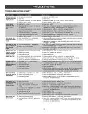
... wiring b) Defective photoelectric sensor Edge Sensor does a) Incorrect edge sensor wiring not stop , and may reverse direction. and COM terminals. Charge batteries by AC or solar power or replace batteries On dual-gate system, incorrect gate opens first or closes first. a) Check for 5 minutes or alarm sounds with a command. a) Incorrect Bipart...
... wiring b) Defective photoelectric sensor Edge Sensor does a) Incorrect edge sensor wiring not stop , and may reverse direction. and COM terminals. Charge batteries by AC or solar power or replace batteries On dual-gate system, incorrect gate opens first or closes first. a) Check for 5 minutes or alarm sounds with a command. a) Incorrect Bipart...

RSL12U Installation Manual
Page 37
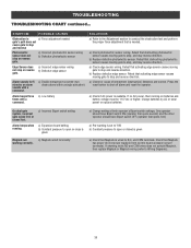
... Controls Program remote controls 1 to 50 to primary Monitor operator. Garage and Gate Program to the primary operator. LiftMaster Program to the secondary operator 36 SYMPTOM Solenoid lock not working correctly, turning off , or resetting. SECONDARY OPERATOR ...board a) Add more solar panels b) Reduce the accessory power draw by using LiftMaster low power accessories c) Replace batteries d) Relocate the solar panels away from obstructions (trees, buildings, etc.) a) Add more solar panels b) Reduce the accessory power draw by using LiftMaster low power accessories c) ...
... Controls Program remote controls 1 to 50 to primary Monitor operator. Garage and Gate Program to the primary operator. LiftMaster Program to the secondary operator 36 SYMPTOM Solenoid lock not working correctly, turning off , or resetting. SECONDARY OPERATOR ...board a) Add more solar panels b) Reduce the accessory power draw by using LiftMaster low power accessories c) Replace batteries d) Relocate the solar panels away from obstructions (trees, buildings, etc.) a) Add more solar panels b) Reduce the accessory power draw by using LiftMaster low power accessories c) ...

RSL12U Installation Manual
Page 38
We recommend LiftMaster low power draw accessories to minimize power draw, refer to ensure proper operation. This is not supported in northern climates where temperatures reach below 32˚F. Cycle rate may vary from solar chart for areas that reach below -4˚F. The gate operator is due to improve performance. Disconnect the expansion...
We recommend LiftMaster low power draw accessories to minimize power draw, refer to ensure proper operation. This is not supported in northern climates where temperatures reach below 32˚F. Cycle rate may vary from solar chart for areas that reach below -4˚F. The gate operator is due to improve performance. Disconnect the expansion...

RSL12U Installation Manual
Page 39
...battery 22 17 16 35 30 28 10 38 Actual results may vary. SOLAR PANEL(S) SOLAR USAGE GUIDE APPENDIX Typical System Standby Battery Current Consumption (mA) System voltage Main board with no radios programmed One or more LiftMaster® remote controls programmed MyQ® device or wireless dual gate programmed ... and accessory to determine total current draw. 12V 4.2 mA +1.5 mA +3.9 mA +18.5 mA +6.6 mA BATTERY CURRENT DRAW (mA) 7AH battery 10W SOLAR PANEL 6 33 25 27 30 26 50 21 100 20W SOLAR PANEL 6 50 (Two 10W 12V panels in 25 50 parallel) 30 50 100 33 200 30W...
...battery 22 17 16 35 30 28 10 38 Actual results may vary. SOLAR PANEL(S) SOLAR USAGE GUIDE APPENDIX Typical System Standby Battery Current Consumption (mA) System voltage Main board with no radios programmed One or more LiftMaster® remote controls programmed MyQ® device or wireless dual gate programmed ... and accessory to determine total current draw. 12V 4.2 mA +1.5 mA +3.9 mA +18.5 mA +6.6 mA BATTERY CURRENT DRAW (mA) 7AH battery 10W SOLAR PANEL 6 33 25 27 30 26 50 21 100 20W SOLAR PANEL 6 50 (Two 10W 12V panels in 25 50 parallel) 30 50 100 33 200 30W...

RSL12U Installation Manual
Page 40
...angle can be mounted using #16 AWG wire in any direction, including elevating it. • DO NOT install solar panel near potential shading or obstructions that do not shade the solar panel(s) in an area clear of the panel(s) is not being charged. TIPS: • Tall trees or ... optimize the system for a 180° arc east to 100 feet (30.48 m) from buildings and trees. Solar Panel (Facing South) South 180° Sun's Position Operator South 39 SOLAR PANEL(S) The location of all obstructions and shading from the operator using the provided angle bracket facing due south. If...
...angle can be mounted using #16 AWG wire in any direction, including elevating it. • DO NOT install solar panel near potential shading or obstructions that do not shade the solar panel(s) in an area clear of the panel(s) is not being charged. TIPS: • Tall trees or ... optimize the system for a 180° arc east to 100 feet (30.48 m) from buildings and trees. Solar Panel (Facing South) South 180° Sun's Position Operator South 39 SOLAR PANEL(S) The location of all obstructions and shading from the operator using the provided angle bracket facing due south. If...

RSL12U Installation Manual
Page 41
...Red Wire (+) 5. Connect the shorter red wire (+) from the control board (it from the J15 plug (new wire harness) labeled DC Power to solar bracket using appropriate hardware. APPENDIX STEP 6 continued... Set the new 33AH battery in track away from the J15 plug (new wire harness) labeled DC Power... the back of the battery. 4. NOTE: You may see a small spark when plugging the J15 plug into the J15 input on the solar panel. Secure solar panel(s) assembly to achieve the desired wattage (30W maximum). Plug the J15 plug (new wire harness) into the board. 10W 10W 10W If...
...Red Wire (+) 5. Connect the shorter red wire (+) from the control board (it from the J15 plug (new wire harness) labeled DC Power to solar bracket using appropriate hardware. APPENDIX STEP 6 continued... Set the new 33AH battery in track away from the J15 plug (new wire harness) labeled DC Power... the back of the battery. 4. NOTE: You may see a small spark when plugging the J15 plug into the J15 input on the solar panel. Secure solar panel(s) assembly to achieve the desired wattage (30W maximum). Plug the J15 plug (new wire harness) into the board. 10W 10W 10W If...

RSL12U Installation Manual
Page 43
... Heater Input Power Connection To Pin 2 To Pin 1 - + - + To Pin 6 To Pin 5 Run Stop/Reset One, two, or three 10W Solar Panels wired in parallel (30W maximum) Red Reset Switch 1/8 HP 12 Vdc Motor EXPANSION BOARD (Optional) APS Encoder Loop Detector OPEN CLOSE POWER 1 EYE ONLY...COM TO MAIN BOARD EYE EDGE OR EYE EDGE OR EYE N.C. For continued protection against fire and electrocution: • DISCONNECT power (AC or solar and battery) BEFORE installing or servicing operator. WIRING DIAGRAM Field Wiring Edge Edge To protect against fire: • Replace ONLY with fuse of ...
... Heater Input Power Connection To Pin 2 To Pin 1 - + - + To Pin 6 To Pin 5 Run Stop/Reset One, two, or three 10W Solar Panels wired in parallel (30W maximum) Red Reset Switch 1/8 HP 12 Vdc Motor EXPANSION BOARD (Optional) APS Encoder Loop Detector OPEN CLOSE POWER 1 EYE ONLY...COM TO MAIN BOARD EYE EDGE OR EYE EDGE OR EYE N.C. For continued protection against fire and electrocution: • DISCONNECT power (AC or solar and battery) BEFORE installing or servicing operator. WIRING DIAGRAM Field Wiring Edge Edge To protect against fire: • Replace ONLY with fuse of ...

RSL12U Installation Manual
Page 46
... battery provided with operator. Requires a 33AH battery harness. Must be remotely installed. Model A12330SGLPK 33AH BATTERY HARNESS Required for solar applications. Model K94-37236 * Available end of remote controls and wireless keyless entries). Model 86LM COMMERCIAL ACCESS CONTROL RECEIVER Access...metal keypad, zinc-alloy metal front cover and 5 year 9V lithium battery. Reuse existing harnesses. Ideal for 33AH applications. LiftMaster low power accessory. Model LD7LP VEHICLE SENSING PROBE The vehicle sensing probe is required for each gate operator. Model MSLM WIRELESS...
... battery provided with operator. Requires a 33AH battery harness. Must be remotely installed. Model A12330SGLPK 33AH BATTERY HARNESS Required for solar applications. Model K94-37236 * Available end of remote controls and wireless keyless entries). Model 86LM COMMERCIAL ACCESS CONTROL RECEIVER Access...metal keypad, zinc-alloy metal front cover and 5 year 9V lithium battery. Reuse existing harnesses. Ideal for 33AH applications. LiftMaster low power accessory. Model LD7LP VEHICLE SENSING PROBE The vehicle sensing probe is required for each gate operator. Model MSLM WIRELESS...


