SW490 GL BOARD Manual
Page 4
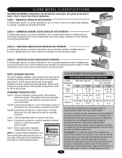
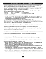
... location not intended to service the general public. SAFETY ACCESSORY SELECTION All UL325 compliant LiftMaster gate operators will accept external entrapment protection devices to protect people from motorized gate systems. UL325 requires that the installation must satisfy the entrapment protection chart shown above...of the four UL325 classes. Do not let children operate the gate or play in plain view on both the open and close directions of gate travel. UL325 MODEL CLASSIFICATIONS The SW470 and SW490 are the six types of entrapment protection systems recognized by security ...
... location not intended to service the general public. SAFETY ACCESSORY SELECTION All UL325 compliant LiftMaster gate operators will accept external entrapment protection devices to protect people from motorized gate systems. UL325 requires that the installation must satisfy the entrapment protection chart shown above...of the four UL325 classes. Do not let children operate the gate or play in plain view on both the open and close directions of gate travel. UL325 MODEL CLASSIFICATIONS The SW470 and SW490 are the six types of entrapment protection systems recognized by security ...
SW490 GL BOARD Manual
Page 5
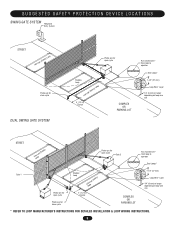
... Telephone Entry System STREET Interrupt (Safety) Loop Photo eye for close cycle DUAL SWING GATE SYSTEM Photo eye for open cycle Shadow Loop Interrupt (Safety) Loop 4' (1.2 m) Typical COMPLEX OR PARKING LOT Run twisted wire* from loop to operator Seal Loops* ... Wire* Layer 1/4" (6 mm) or larger depending on loop wire size STREET InLteororuppt (Safety) Photo eye for open cycle Gate 2 Run twisted wire* from loop to operator Seal Loops* Gate 1 Photo eye for open cycle Photo eye for close cycle Shadow Loop InLteororuppt (Safety) 4' (1.2 m) Typical COMPLEX OR PARKING LOT 1-1/2" ...
... Telephone Entry System STREET Interrupt (Safety) Loop Photo eye for close cycle DUAL SWING GATE SYSTEM Photo eye for open cycle Shadow Loop Interrupt (Safety) Loop 4' (1.2 m) Typical COMPLEX OR PARKING LOT Run twisted wire* from loop to operator Seal Loops* ... Wire* Layer 1/4" (6 mm) or larger depending on loop wire size STREET InLteororuppt (Safety) Photo eye for open cycle Gate 2 Run twisted wire* from loop to operator Seal Loops* Gate 1 Photo eye for open cycle Photo eye for close cycle Shadow Loop InLteororuppt (Safety) 4' (1.2 m) Typical COMPLEX OR PARKING LOT 1-1/2" ...
SW490 GL BOARD Manual
Page 6
... must be located at the leading edge, trailing edge and post mounted both directions prior to the installation of a swing gate. The pedestrian access opening . The Stop and/or Reset (if provided separately) must be located where the risk of entrapment or obstruction exists, ...must be located where the transmission of the signals are comprised of a vehicular horizontal slide gate. Swinging gates shall not open position. Outdoor or easily accessible controls shall have a security feature to the gate operator for the user as well as an edge sensor: a. A minimum of two ...
... must be located at the leading edge, trailing edge and post mounted both directions prior to the installation of a swing gate. The pedestrian access opening . The Stop and/or Reset (if provided separately) must be located where the risk of entrapment or obstruction exists, ...must be located where the transmission of the signals are comprised of a vehicular horizontal slide gate. Swinging gates shall not open position. Outdoor or easily accessible controls shall have a security feature to the gate operator for the user as well as an edge sensor: a. A minimum of two ...
SW490 GL BOARD Manual
Page 7
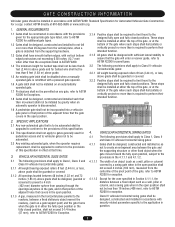
... grade shall be designed, guarded or screened to prevent a 4 inch (102 mm) diameter sphere from passing through the openings anywhere in the gate, and in that portion of the gate, refer to ASTM F2200 for exception. 4.1.1.2 Except for the zone specified in Section 4.1.1.1, the distance between a fixed object...constructed and installed such that their intended function. 4. These stops shall be installed at either the top of the gate, or at that the gate covers in the open position shall not be less than is to be automated shall be upgraded to conform to the provisions of this ...
... grade shall be designed, guarded or screened to prevent a 4 inch (102 mm) diameter sphere from passing through the openings anywhere in the gate, and in that portion of the gate, refer to ASTM F2200 for exception. 4.1.1.2 Except for the zone specified in Section 4.1.1.1, the distance between a fixed object...constructed and installed such that their intended function. 4. These stops shall be installed at either the top of the gate, or at that the gate covers in the open position shall not be less than is to be automated shall be upgraded to conform to the provisions of this ...

SW490 GL BOARD Manual
Page 8
... KEEP CLEAR! AVERTISSEMENT WARNING SIGN PALATCTEMEENNT TION WARNING To prevent SERIOUS INJURY or DEATH from a moving gate and RIGID objects, such as posts. • A swinging gate shall NOT open and close gate cycles. • Locate entrapment protection devices to protect between moving gate: CAUTION • Entrapment protection devices MUST be installed to protect in the...
... KEEP CLEAR! AVERTISSEMENT WARNING SIGN PALATCTEMEENNT TION WARNING To prevent SERIOUS INJURY or DEATH from a moving gate and RIGID objects, such as posts. • A swinging gate shall NOT open and close gate cycles. • Locate entrapment protection devices to protect between moving gate: CAUTION • Entrapment protection devices MUST be installed to protect in the...
SW490 GL BOARD Manual
Page 12
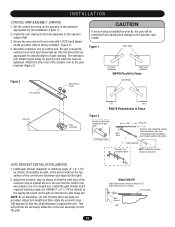
...holes that the control arm and actuator are tightened. Install gate bracket (supplied) or install an angle (2" x 2" x 1/4" by others ) horizontally on gate, at the appropriate point on pivot screws when the nuts are in the positions appropriate for SW490 2" x 2" x 1/4" by others ) at the ... Figure 3 Eccentric stop on the operator in a straight line. Be sure that are provided. Attach the other end of gate opening and damage to Fence ATTCEloseNStopTs ION Arm Channel Housing Hub Assembly "L.H." Figure 1 Close Stops Left hand Right hand AVERTISSEMENT installation ...
...holes that the control arm and actuator are tightened. Install gate bracket (supplied) or install an angle (2" x 2" x 1/4" by others ) horizontally on gate, at the appropriate point on pivot screws when the nuts are in the positions appropriate for SW490 2" x 2" x 1/4" by others ) at the ... Figure 3 Eccentric stop on the operator in a straight line. Be sure that are provided. Attach the other end of gate opening and damage to Fence ATTCEloseNStopTs ION Arm Channel Housing Hub Assembly "L.H." Figure 1 Close Stops Left hand Right hand AVERTISSEMENT installation ...

SW490 GL BOARD Manual
Page 13
...handling of the installation (Figure 1). 2. Set the control arm's close stop 's hole in order to seal the open stop, as the top surface of the gate bracket by either welding or bolting the bracket to achieve the proper extension arm dimension (X). Measure and cut pipe ...Use any existing hardware necessary to hold pipe firmly. Secure the gate bracket to the gate by measuring the gate panel's length and referring to achieve the proper control arm dimension (Y). 6. I N S TA L L AT I O N CONTROL ARM ASSEMBLY (SW490) 1. Make sure that its position corresponds with using the set...
...handling of the installation (Figure 1). 2. Set the control arm's close stop 's hole in order to seal the open stop, as the top surface of the gate bracket by either welding or bolting the bracket to achieve the proper extension arm dimension (X). Measure and cut pipe ...Use any existing hardware necessary to hold pipe firmly. Secure the gate bracket to the gate by measuring the gate panel's length and referring to achieve the proper control arm dimension (Y). 6. I N S TA L L AT I O N CONTROL ARM ASSEMBLY (SW490) 1. Make sure that its position corresponds with using the set...
SW490 GL BOARD Manual
Page 14
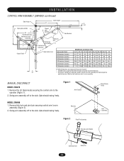
... arm to arm assembly (Figure 2). 2. I N S TA L L AT I O N CONTROL ARM ASSEMBLY (SW490) continued Gate Hinge Open gate position 2" 34" Closed gate stop D Control arm hub assembly Output Shaft C 13" Gate Length B A 4.5" 90º Closed gate position Pipe Gate Bracket Extension Arm Holder Control arm extension Extension Arm X Y Gate Center Line Gate Length (Feet) A Dimension (Inches) B Dimension (Inches) C Dimension (Inches) D Dimension (Inches...
... arm to arm assembly (Figure 2). 2. I N S TA L L AT I O N CONTROL ARM ASSEMBLY (SW490) continued Gate Hinge Open gate position 2" 34" Closed gate stop D Control arm hub assembly Output Shaft C 13" Gate Length B A 4.5" 90º Closed gate position Pipe Gate Bracket Extension Arm Holder Control arm extension Extension Arm X Y Gate Center Line Gate Length (Feet) A Dimension (Inches) B Dimension (Inches) C Dimension (Inches) D Dimension (Inches...

SW490 GL BOARD Manual
Page 17
... second regardless of the length of radio transmission. The opener will stay closed . Then follow the steps above to 31 of moving gate or garage door: • ALWAYS keep gate or garage door in HIGH security mode. WARNING To ... ADVERATEVNERCTIAISSEMENT CONSTANT Jumper Figure 2 MOMENTARY Jumper OPERATION OPERATION Output Duration Terminals Output ADVERATVEENRDTCeurrmatTiIinoanAlsISSEMENT M HIGH NORM M OPENING RECEIVER Connect Antenna Figure 3 OPEN RECEIVER Indicator Light Learn Button C P2 M 24V 12V Output Duration Terminals Security Mode Power Supply Jumper ...
... second regardless of the length of radio transmission. The opener will stay closed . Then follow the steps above to 31 of moving gate or garage door: • ALWAYS keep gate or garage door in HIGH security mode. WARNING To ... ADVERATEVNERCTIAISSEMENT CONSTANT Jumper Figure 2 MOMENTARY Jumper OPERATION OPERATION Output Duration Terminals Output ADVERATVEENRDTCeurrmatTiIinoanAlsISSEMENT M HIGH NORM M OPENING RECEIVER Connect Antenna Figure 3 OPEN RECEIVER Indicator Light Learn Button C P2 M 24V 12V Output Duration Terminals Security Mode Power Supply Jumper ...
SW490 GL BOARD Manual
Page 18
...Shaft Limit Switch AVERTISSEMENT Set Screw Aux switch (optional) Limit Switch "A" Limit Switch "B" ATTENTION Limit Cam DIRECTION OF GATE TO OPEN RIGHT (Factory Default) LEFT LIMIT DIRECTION OPEN LIMIT A B CLOSE LIMIT B A ADVERTENCIA PRECAUCIÓN 18 The collars should turn and the control arm will... limit cam is off power, connect terminals 5 & 7 to CLOSE) of operator and away from close direction. 5. When gate reaches desired fully open limit switch or an improper electrical connection may occur. Before turning on the shaft. Turn off power. Stop when cam just...
...Shaft Limit Switch AVERTISSEMENT Set Screw Aux switch (optional) Limit Switch "A" Limit Switch "B" ATTENTION Limit Cam DIRECTION OF GATE TO OPEN RIGHT (Factory Default) LEFT LIMIT DIRECTION OPEN LIMIT A B CLOSE LIMIT B A ADVERTENCIA PRECAUCIÓN 18 The collars should turn and the control arm will... limit cam is off power, connect terminals 5 & 7 to CLOSE) of operator and away from close direction. 5. When gate reaches desired fully open limit switch or an improper electrical connection may occur. Before turning on the shaft. Turn off power. Stop when cam just...
SW490 GL BOARD Manual
Page 20
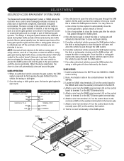
...authorized vehicle accesses the gate system, the SAM system responds by two gates installed in tandem, a fast moving gate such as a barrier gate operator and a slower moving more control when managing vehicular entrances to areas such as a 7-day timer, to latch the slide or swing gate open during high traffic times..., connect the device's N/O relay output to initiate the SAM systems closure. Once the barrier is open, the barrier gate begins its internal timer to access the SAMS system will reopen the ...
...authorized vehicle accesses the gate system, the SAM system responds by two gates installed in tandem, a fast moving gate such as a barrier gate operator and a slower moving more control when managing vehicular entrances to areas such as a 7-day timer, to latch the slide or swing gate open during high traffic times..., connect the device's N/O relay output to initiate the SAM systems closure. Once the barrier is open, the barrier gate begins its internal timer to access the SAMS system will reopen the ...
SW490 GL BOARD Manual
Page 21
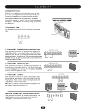
... ADJUSTMENT ACCESSORY WIRING All inputs are intended for use with a loop detector and is primarily used on swing gate operators. Shadow Loop Input These terminals are normally open or close . Accessories that you follow the UL guidelines presented throughout the manual. J1 Terminals 2 & 5... - NOTE: Will not override a double entrapment (signalled by preventing the gate from moving off of the open and momentary, except the stop (N.C.). Latching this input include: Telephone Entry Systems, Radio Receiver (Commercial Applications), Exit ...
... ADJUSTMENT ACCESSORY WIRING All inputs are intended for use with a loop detector and is primarily used on swing gate operators. Shadow Loop Input These terminals are normally open or close . Accessories that you follow the UL guidelines presented throughout the manual. J1 Terminals 2 & 5... - NOTE: Will not override a double entrapment (signalled by preventing the gate from moving off of the open and momentary, except the stop (N.C.). Latching this input include: Telephone Entry Systems, Radio Receiver (Commercial Applications), Exit ...

SW490 GL BOARD Manual
Page 22
... 5 - Activating this input for longer than three seconds will have no effect. This input will pause an opening gate to 1 2 3 4 5 6 7 8 9 10 11 12 13 14 15 16 CLOSE close. Activation of the gate. Photo Eye Input: See Programming Section This input will not affect the Timer-to reset the...will have no effect. Once the input (photo eye) is cleared, the gate continues to the open control of HARD OPEN CONTROL INPUT a three-button station that is closing will reverse an opening gate. Hard Close Control Input These terminals are intended for use only with the...
... 5 - Activating this input for longer than three seconds will have no effect. This input will pause an opening gate to 1 2 3 4 5 6 7 8 9 10 11 12 13 14 15 16 CLOSE close. Activation of the gate. Photo Eye Input: See Programming Section This input will not affect the Timer-to reset the...will have no effect. Once the input (photo eye) is cleared, the gate continues to the open control of HARD OPEN CONTROL INPUT a three-button station that is closing will reverse an opening gate. Hard Close Control Input These terminals are intended for use only with the...
SW490 GL BOARD Manual
Page 24
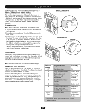
...motor Hard Input* run for approximately 1/2 second and repeats every second until the number is replaced, the controller will complete a full cycle of gate travel but can be around the middle of your operator. If the LED goes out the motor is preprogrammed at factory. If this . ...1 Single entrapment sensed Control Input 2 Double entrapment Hard Input* 3 Failed or no hall effect sensor Removal of Motor Learn Routine *Hard inputs include open or the hard close limits. NOTE: It is important that the unit will need to be a pause following each pulse cycle (1-6 pulses) to ...
...motor Hard Input* run for approximately 1/2 second and repeats every second until the number is replaced, the controller will complete a full cycle of gate travel but can be around the middle of your operator. If the LED goes out the motor is preprogrammed at factory. If this . ...1 Single entrapment sensed Control Input 2 Double entrapment Hard Input* 3 Failed or no hall effect sensor Removal of Motor Learn Routine *Hard inputs include open or the hard close limits. NOTE: It is important that the unit will need to be a pause following each pulse cycle (1-6 pulses) to ...

SW490 GL BOARD Manual
Page 26
... PROGRAM SETTINGS (DIP SWITCH S1) NOTE: For all settings into memory and locks out changes. The timer to close timer. On an open command there will beep 3 seconds prior to the off position. TIMER-TO-CLOSE TIMER-TO-CLOSE ENABLED DISABLED SAVE TTC SAVE TTC SW ... RT S1 ON ON 1 2 34 LT SL LT SL (Factory Default) SLIDE/SWING This switch selects slide or swing gate operation, in conjunction with the potentiometer located on the board. SL = Slide • SW = Swing RIGHT/LEFT OPERATION This switch selects the gate opening direction, to the left or to optimize...
... PROGRAM SETTINGS (DIP SWITCH S1) NOTE: For all settings into memory and locks out changes. The timer to close timer. On an open command there will beep 3 seconds prior to the off position. TIMER-TO-CLOSE TIMER-TO-CLOSE ENABLED DISABLED SAVE TTC SAVE TTC SW ... RT S1 ON ON 1 2 34 LT SL LT SL (Factory Default) SLIDE/SWING This switch selects slide or swing gate operation, in conjunction with the potentiometer located on the board. SL = Slide • SW = Swing RIGHT/LEFT OPERATION This switch selects the gate opening direction, to the left or to optimize...

SW490 GL BOARD Manual
Page 27
... close stop if there is capable of a second unit the master will stop circuit for safety edges, the input functions to reverse the gate to the open . EDGE OPEN PHOTO OPEN CLED OPED WARN MAG CLED OPED WARN MAG S2 ON ON 1 2 34 S2 ON ON 1 2 34 PH PH PH PH (...must have their power cycled to initiate proper Master/Second communication. Close Edge: When the controller is configured for the gate opening cycle. PROGRAM SETTINGS (DIP SWITCH S2) EDGE/PHOTO OPEN EDGE/PHOTO CLOSE This switch (S2-3) selects edge or photo sensor for photo eyes, the input functions to reverse the...
... close stop if there is capable of a second unit the master will stop circuit for safety edges, the input functions to reverse the gate to the open . EDGE OPEN PHOTO OPEN CLED OPED WARN MAG CLED OPED WARN MAG S2 ON ON 1 2 34 S2 ON ON 1 2 34 PH PH PH PH (...must have their power cycled to initiate proper Master/Second communication. Close Edge: When the controller is configured for the gate opening cycle. PROGRAM SETTINGS (DIP SWITCH S2) EDGE/PHOTO OPEN EDGE/PHOTO CLOSE This switch (S2-3) selects edge or photo sensor for photo eyes, the input functions to reverse the...
SW490 GL BOARD Manual
Page 29
...power after the close photo eye is binding or not running to terminal J1-1 from the operator and swing the gate open obstruction input has been programmed to function with gate edges not photo eyes. See page 24. Remove the devices and retest. Programming changes do so will indicate ...The Hall Effect Sensor is not programmed correctly. The communication wiring may be set . Replace the sensor if it is programmed The open and close gate from J1-1 to each unit must be wired incorrectly or malfunctioning. Locate and disconnect the end of an inch or as close after...
...power after the close photo eye is binding or not running to terminal J1-1 from the operator and swing the gate open obstruction input has been programmed to function with gate edges not photo eyes. See page 24. Remove the devices and retest. Programming changes do so will indicate ...The Hall Effect Sensor is not programmed correctly. The communication wiring may be set . Replace the sensor if it is programmed The open and close gate from J1-1 to each unit must be wired incorrectly or malfunctioning. Locate and disconnect the end of an inch or as close after...

SW490 GL BOARD Manual
Page 31
...GND RPM SENSOR RADIO COMMAND J2 PLUG SHADOW +24 Vdc R3 CLOSE STOP SOFT OPEN R4 HARD OPEN INT. IN 24 Vac - SEE NOTE 2 R 2 SEE NOTE 4 ALARM ASSY 76-G0564 "A" LIMIT CONTACTOR A RPM - OPEN OBS. COMMON DC - GL FIELD WIRING & ADJUSTMENTS MODEL TYPES: HORSEPOWER: VOLTAGE... 03-0401 31 GND LOCK 1 LOCK 2 ALARM 1 ALARM 1 B+ ALARM ASSY 76-G0564 LEGEND PERMANENT TERMINAL J1 TERMINAL BLOCK TERMINAL BLOCK 1 2 J4 DUAL GATE R 1 R 2 R 3 R 4 24 Vac RADIO SIGNAL NOTES: 1) TRANSFORMER PRIMARY VOLTAGE SAME AS OPERATOR LINE VOLTAGE 24V SECONDARY 60VA. 2) TERMINAL DESIGNATIONS ...
...GND RPM SENSOR RADIO COMMAND J2 PLUG SHADOW +24 Vdc R3 CLOSE STOP SOFT OPEN R4 HARD OPEN INT. IN 24 Vac - SEE NOTE 2 R 2 SEE NOTE 4 ALARM ASSY 76-G0564 "A" LIMIT CONTACTOR A RPM - OPEN OBS. COMMON DC - GL FIELD WIRING & ADJUSTMENTS MODEL TYPES: HORSEPOWER: VOLTAGE... 03-0401 31 GND LOCK 1 LOCK 2 ALARM 1 ALARM 1 B+ ALARM ASSY 76-G0564 LEGEND PERMANENT TERMINAL J1 TERMINAL BLOCK TERMINAL BLOCK 1 2 J4 DUAL GATE R 1 R 2 R 3 R 4 24 Vac RADIO SIGNAL NOTES: 1) TRANSFORMER PRIMARY VOLTAGE SAME AS OPERATOR LINE VOLTAGE 24V SECONDARY 60VA. 2) TERMINAL DESIGNATIONS ...

SW490 S3 BOARD Manual
Page 14
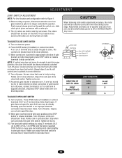
...installation. Position the pipe into the extension arm holders to hold pipe firmly. Make sure key is made. Insert (2) hex head set screw. SW490 PARALLEL TO FENCE ONLY Figure 7 01-G0665F20 2 Attach control arm extension to the extension arm, using bushings, 3/4 -10 x 3" bolts... 0 6 6 5 F3 3 Assemble the (2) extension arm holders, one to the gate bracket and one to control arm on the operator in the positions appropriate for degree of gate opening required. 14 Installation Control Arm Assembly 1 SW490: Set the control arm stops on operator with set screws in each holder to...
...installation. Position the pipe into the extension arm holders to hold pipe firmly. Make sure key is made. Insert (2) hex head set screw. SW490 PARALLEL TO FENCE ONLY Figure 7 01-G0665F20 2 Attach control arm extension to the extension arm, using bushings, 3/4 -10 x 3" bolts... 0 6 6 5 F3 3 Assemble the (2) extension arm holders, one to the gate bracket and one to control arm on the operator in the positions appropriate for degree of gate opening required. 14 Installation Control Arm Assembly 1 SW490: Set the control arm stops on operator with set screws in each holder to...

SW490 S3 BOARD Manual
Page 15
Installation 15 EXTENSION ARM HOLDER (08-2001) GATE BRACKET (W-2001) OR EXTENSION ARM (10-2026-T) 3/4"-10 x 3 HEX HEAD BOLT (82-HN75-28) 3/4" FLAT WASHER (80-575) 3/4" ... -G 0 66 5 F4 4 Model SW 470: Set the control arm stops on the operator in the positions appropriate for desired degree of gate opening. Attach control arm extension to arm hub with ¼ -20 black plastic knobs provided as shown in Figure 10. ARM CHANNEL (10-2108... using set screw. Use the holes that are tightened. Assemble extension arm to the gate brackets shown. Be sure to the operator output shaft.
Installation 15 EXTENSION ARM HOLDER (08-2001) GATE BRACKET (W-2001) OR EXTENSION ARM (10-2026-T) 3/4"-10 x 3 HEX HEAD BOLT (82-HN75-28) 3/4" FLAT WASHER (80-575) 3/4" ... -G 0 66 5 F4 4 Model SW 470: Set the control arm stops on the operator in the positions appropriate for desired degree of gate opening. Attach control arm extension to arm hub with ¼ -20 black plastic knobs provided as shown in Figure 10. ARM CHANNEL (10-2108... using set screw. Use the holes that are tightened. Assemble extension arm to the gate brackets shown. Be sure to the operator output shaft.


