
SW490 GL BOARD Manual
Page 1
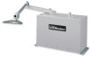
MODEL SW470 MEDIUM DUTY SWING GATE OPERATOR GLCONTROLLER BOARD MODEL SW490 HEAVY DUTY SWING GATE OPERATOR 2 YEAR WARRANTY Serial located on electrical box cover) Installation Date INTENDED FOR PROFESSIONAL INSTALLATION ONLY. MODELS SW470 AND SW490 ARE FOR VEHICULAR PASSAGE GATES ONLY AND NOT INTENDED FOR PEDESTRIAN PASSAGE GATE USE. THIS MANUAL IS TO BE LEFT WITH THE PROPERTY OWNER. VISIT WWW.LIFTMASTER.COM TO LOCATE A PROFESSIONAL INSTALLING DEALER IN YOUR AREA.
MODEL SW470 MEDIUM DUTY SWING GATE OPERATOR GLCONTROLLER BOARD MODEL SW490 HEAVY DUTY SWING GATE OPERATOR 2 YEAR WARRANTY Serial located on electrical box cover) Installation Date INTENDED FOR PROFESSIONAL INSTALLATION ONLY. MODELS SW470 AND SW490 ARE FOR VEHICULAR PASSAGE GATES ONLY AND NOT INTENDED FOR PEDESTRIAN PASSAGE GATE USE. THIS MANUAL IS TO BE LEFT WITH THE PROPERTY OWNER. VISIT WWW.LIFTMASTER.COM TO LOCATE A PROFESSIONAL INSTALLING DEALER IN YOUR AREA.
SW490 GL BOARD Manual
Page 2
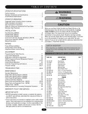
...1 85-LS-38 3/8 Lockwasher 2 86-CP05-300 Cotter Pin 2 2 WARNING Mechanical CWWAUAATRRINNOIINNNGG Electrical CAWUATRIONNING When you see this manual and follow all safety instructions. • These instructions are not intended to ensure that accompany it is safe for factory supplied parts...Placement 8 INSTALLATION Post Mounting (SW470 9 Pad Mounting (SW470 10 Pad Mounting (SW490 11 Control Arm and Gate Bracket Installation (SW470 12 Control Arm Assembly (SW490 13-14 Manual Disconnect 14 WIRING AVERTISSEMENT Power Wiring Installation 15 On/Off Switch Power Wiring 16 ...
...1 85-LS-38 3/8 Lockwasher 2 86-CP05-300 Cotter Pin 2 2 WARNING Mechanical CWWAUAATRRINNOIINNNGG Electrical CAWUATRIONNING When you see this manual and follow all safety instructions. • These instructions are not intended to ensure that accompany it is safe for factory supplied parts...Placement 8 INSTALLATION Post Mounting (SW470 9 Pad Mounting (SW470 10 Pad Mounting (SW490 11 Control Arm and Gate Bracket Installation (SW470 12 Control Arm Assembly (SW490 13-14 Manual Disconnect 14 WIRING AVERTISSEMENT Power Wiring Installation 15 On/Off Switch Power Wiring 16 ...
SW490 GL BOARD Manual
Page 6
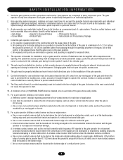
... with the vehicular gate during the entire path of travel of travel, one on the bottom edge. Swinging gates shall not open position. Reference owner's manual regarding placement of non-contact sensor for the user as well as the perimeter reachable by building structures, natural landscaping or similar obstruction. Install the...
... with the vehicular gate during the entire path of travel of travel, one on the bottom edge. Swinging gates shall not open position. Reference owner's manual regarding placement of non-contact sensor for the user as well as the perimeter reachable by building structures, natural landscaping or similar obstruction. Install the...
SW490 GL BOARD Manual
Page 7
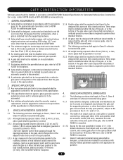
... Class IV vehicular horizontal slide gates: 3.2.1 All weight bearing exposed rollers 8 feet (2.44 m), or less, above grade. 1.5 An existing gate latch shall be disabled when a manually operated gate is retrofitted with a powered gate operator. 1.6 A gate latch shall not be installed on an automatically operated gate. 1.7 Protrusions shall not be permitted on...
... Class IV vehicular horizontal slide gates: 3.2.1 All weight bearing exposed rollers 8 feet (2.44 m), or less, above grade. 1.5 An existing gate latch shall be disabled when a manually operated gate is retrofitted with a powered gate operator. 1.6 A gate latch shall not be installed on an automatically operated gate. 1.7 Protrusions shall not be permitted on...
SW490 GL BOARD Manual
Page 14
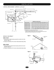
... arm assembly off to the side. Remove the (2) black knobs securing the control arm to arm assembly. Figure 1 Arm Channel MODEL SW490 1. Gate should swing freely. Gate should swing freely. MANUAL DISCONNECT MODEL SW470 1. Remove hitch pin and pivot pin securing control arm to pivot dimension. Housing Black Plastic Knob Hub Assembly...
... arm assembly off to the side. Remove the (2) black knobs securing the control arm to arm assembly. Figure 1 Arm Channel MODEL SW490 1. Gate should swing freely. Gate should swing freely. MANUAL DISCONNECT MODEL SW470 1. Remove hitch pin and pivot pin securing control arm to pivot dimension. Housing Black Plastic Knob Hub Assembly...
SW490 GL BOARD Manual
Page 18
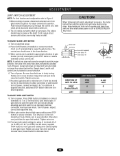
... J1 terminal strip to cause the gate to operator. ADJUSTMENT WARNING LIMIT SWITCH ADJUSTMENT NOTE: For limit location and configuration refer to extension arm. Push manual release pin(s) up through the control arm, slide clevis pin in correct direction. 6. Press CLOSE button (if installed) or connect terminals 4 & 5 on power, disconnect extension...
... J1 terminal strip to cause the gate to operator. ADJUSTMENT WARNING LIMIT SWITCH ADJUSTMENT NOTE: For limit location and configuration refer to extension arm. Push manual release pin(s) up through the control arm, slide clevis pin in correct direction. 6. Press CLOSE button (if installed) or connect terminals 4 & 5 on power, disconnect extension...

SW490 GL BOARD Manual
Page 19
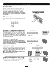
...cm) away from the pulley's magnet. MODEL SW470 Hall Effect Cable Mounting Screw (2) AVERTISSEMENT ATTENTION Hall Effect Bracket Pulley Magnet Pulley MODEL SW490 Mounting Screw (2) Mounting Bracket Hall Effect Cable ADVERTENCIA PRECAPMuUalglenyeCt IÓN Pulley Hall Effect Magnet 19 WARNING To reduce the risk of the ...NOTE: Normally the RPM sensor (hall effect) does not need adjustment, but may become necessary to adjust the sensor for correct alignment. Manually rotate pulley to ensure that the sensor is: a. It may go out of alignment due to measure the distance. 3. If a ...
...cm) away from the pulley's magnet. MODEL SW470 Hall Effect Cable Mounting Screw (2) AVERTISSEMENT ATTENTION Hall Effect Bracket Pulley Magnet Pulley MODEL SW490 Mounting Screw (2) Mounting Bracket Hall Effect Cable ADVERTENCIA PRECAPMuUalglenyeCt IÓN Pulley Hall Effect Magnet 19 WARNING To reduce the risk of the ...NOTE: Normally the RPM sensor (hall effect) does not need adjustment, but may become necessary to adjust the sensor for correct alignment. Manually rotate pulley to ensure that the sensor is: a. It may go out of alignment due to measure the distance. 3. If a ...
SW490 GL BOARD Manual
Page 21
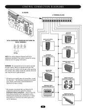
... with optional control devices for use with a loop detector and is on radio terminal block. Accessories that you follow the UL guidelines presented throughout the manual. R1 R2 R3 R4 Control Board 24 Vac J1 Terminals 1 & 5 - The following instructions are normally open limit. INTERRUPT (SAFETY) LOOP INPUT 5 8 9 10 11 12 FREQ...
... with optional control devices for use with a loop detector and is on radio terminal block. Accessories that you follow the UL guidelines presented throughout the manual. R1 R2 R3 R4 Control Board 24 Vac J1 Terminals 1 & 5 - The following instructions are normally open limit. INTERRUPT (SAFETY) LOOP INPUT 5 8 9 10 11 12 FREQ...

SW490 GL BOARD Manual
Page 28
...the two units is making excessive noise. Motor runs but gate Damaged or improperly tensioned does not move . If any distortion or signs of this manual. An installed accessory may be within 5% of the operator's rating when running . Measure the voltage at the operator should be within 5% of... used for any red LEDs are correct replace the transformer. Follow the directions on the board. It should be within 5% of this manual. If breaker and tap are on page 15 of 24 Vac. Make sure that the communication wiring between breaker and operator by consulting ...
...the two units is making excessive noise. Motor runs but gate Damaged or improperly tensioned does not move . If any distortion or signs of this manual. An installed accessory may be within 5% of the operator's rating when running . Measure the voltage at the operator should be within 5% of... used for any red LEDs are correct replace the transformer. Follow the directions on the board. It should be within 5% of this manual. If breaker and tap are on page 15 of 24 Vac. Make sure that the communication wiring between breaker and operator by consulting ...

SW490 GL BOARD Manual
Page 30
...for proper adjustment X X External Entrapment Check for proper operation X X Protection Systems Gate Caution Signs Make sure they are present X X Manual Disconnect Check and operate X X Drive Chain Check for excessive slack and lubricate X X Sprockets and Pulleys Check for excessive slack and ...4. After adjusting the force or the 9. ALL maintenance MUST be taken at the site voltage readings be performed by a LiftMaster limit of the operators rating. 30 Severe or high cycle usage will require more frequent maintenance checks. 2. When servicing, please...
...for proper adjustment X X External Entrapment Check for proper operation X X Protection Systems Gate Caution Signs Make sure they are present X X Manual Disconnect Check and operate X X Drive Chain Check for excessive slack and lubricate X X Sprockets and Pulleys Check for excessive slack and ...4. After adjusting the force or the 9. ALL maintenance MUST be taken at the site voltage readings be performed by a LiftMaster limit of the operators rating. 30 Severe or high cycle usage will require more frequent maintenance checks. 2. When servicing, please...
SW490 GL BOARD Manual
Page 34
... operate the gate system, MUST be installed where the user cannot come into contact with kit for wiring distances and wire gauge information. See owner's manual for additional information. Installation device instructions - CONTROL CONNECTION DIAGRAMS GL BOARD J1 TERMINAL BLOCK 1 2 3 4 5 6 7 8 9 10 11 12 13 14 15 16 24 Vac ACCESSORY POWER... the gate while operating the controls. If these instructions are normally open and momentary, except the stop (N.C.). always follow the UL guidelines presented throughout the manual.
... operate the gate system, MUST be installed where the user cannot come into contact with kit for wiring distances and wire gauge information. See owner's manual for additional information. Installation device instructions - CONTROL CONNECTION DIAGRAMS GL BOARD J1 TERMINAL BLOCK 1 2 3 4 5 6 7 8 9 10 11 12 13 14 15 16 24 Vac ACCESSORY POWER... the gate while operating the controls. If these instructions are normally open and momentary, except the stop (N.C.). always follow the UL guidelines presented throughout the manual.

SW490 S3 BOARD Manual
Page 2
... 17 Electrical Power Connections 18 Programming 19 Switch #1: Operator Programming 19 Switch #2: Timer to Close 20 Controls and Accessory Installation 21 Manual Operation and System Check-Out 22 SW470 Manual Gate Operation 22 Preliminary System Check Out 22 Required Maintenance - Normal Usage 23 Troubleshooting 24 SW470 Parts List and Drawing 25 SW470...
... 17 Electrical Power Connections 18 Programming 19 Switch #1: Operator Programming 19 Switch #2: Timer to Close 20 Controls and Accessory Installation 21 Manual Operation and System Check-Out 22 SW470 Manual Gate Operation 22 Preliminary System Check Out 22 Required Maintenance - Normal Usage 23 Troubleshooting 24 SW470 Parts List and Drawing 25 SW470...

SW490 S3 BOARD Manual
Page 3
This gate operator is intended for use on a gate that swings in an arc in a horizontal plane. Please leave this manual at the job site, preferably with the end user or facility manager. Contents 3 SW470 Parts List 26 SW490 Parts List and Drawing 27 SW490 Exploded View 27 SW490 Parts List 28 Warranty Policy 30 IMPORTANT! Doc 01-G0665 Rev C Read and follow all instructions.
This gate operator is intended for use on a gate that swings in an arc in a horizontal plane. Please leave this manual at the job site, preferably with the end user or facility manager. Contents 3 SW470 Parts List 26 SW490 Parts List and Drawing 27 SW490 Exploded View 27 SW490 Parts List 28 Warranty Policy 30 IMPORTANT! Doc 01-G0665 Rev C Read and follow all instructions.
SW490 S3 BOARD Manual
Page 4
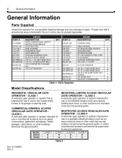
... public. RESTRICTED ACCESS VEHICULAR GATE OPERATOR - CLASS 4 A vehicular gate operator or system intended for use in one to service the general public. MODEL SW470 SW490 CLASS 1 ! ! Table 2 Doc 01-G0665 Rev C CLASS 2 A vehicular gate operator or system intended for use in an industrial location such as ...2109 10-2111 40-3505 80-2103 82-HN38-20 82-SB50-08 84-WH-38 85-FW-38 SW470 DESCRIPTION GATE OPERATIONAL SAFETY INSTRUCTION MANUAL STOP BUTTON ARM CHANNEL EXTENSION ARM GATE BRACKET DORCMA WARNING SIGN BLACK PLASTIC KNOB 3/8-16 x 1-1/2 HEX HEAD BOLT 1/2-13 x 1/2 SHOULDER ...
... public. RESTRICTED ACCESS VEHICULAR GATE OPERATOR - CLASS 4 A vehicular gate operator or system intended for use in one to service the general public. MODEL SW470 SW490 CLASS 1 ! ! Table 2 Doc 01-G0665 Rev C CLASS 2 A vehicular gate operator or system intended for use in an industrial location such as ...2109 10-2111 40-3505 80-2103 82-HN38-20 82-SB50-08 84-WH-38 85-FW-38 SW470 DESCRIPTION GATE OPERATIONAL SAFETY INSTRUCTION MANUAL STOP BUTTON ARM CHANNEL EXTENSION ARM GATE BRACKET DORCMA WARNING SIGN BLACK PLASTIC KNOB 3/8-16 x 1-1/2 HEX HEAD BOLT 1/2-13 x 1/2 SHOULDER ...

SW490 S3 BOARD Manual
Page 6
...Selected Instructions are comprised of operator. 9 To avoid installation hazards, review the gate system operation and installation procedures, such as manual disconnect mechanism procedure. 10 Confirm control design prohibits unauthorized use . 2 Confirm ALL appropriate safety features, such as a component ... vehicular entrance. 5 Confirm gate system design reduces traffic backup. 6 Confirm warning signage is specified by Installation and Maintenance Manual for an individual application. The gate operator is specifically designed for application type, gate size and frequency of use . ...
...Selected Instructions are comprised of operator. 9 To avoid installation hazards, review the gate system operation and installation procedures, such as manual disconnect mechanism procedure. 10 Confirm control design prohibits unauthorized use . 2 Confirm ALL appropriate safety features, such as a component ... vehicular entrance. 5 Confirm gate system design reduces traffic backup. 6 Confirm warning signage is specified by Installation and Maintenance Manual for an individual application. The gate operator is specifically designed for application type, gate size and frequency of use . ...

SW490 S3 BOARD Manual
Page 7
... page 8. Precautions must be aware of all safety features. 2 Train end user about basic functions and safety features of gate system. 3 Leave Installation and Maintenance Manual and Safety Information with end user. When using a sensor with a gate edge transmitter, care must be incorporated into the system. If there are multiple areas...
... page 8. Precautions must be aware of all safety features. 2 Train end user about basic functions and safety features of gate system. 3 Leave Installation and Maintenance Manual and Safety Information with end user. When using a sensor with a gate edge transmitter, care must be incorporated into the system. If there are multiple areas...

SW490 S3 BOARD Manual
Page 11
... the operator to a complete stop and alarm. Doc 01-G0665 Rev C NOTE: If external entrapment protection is the main circuit board for the system. Either a manual device such as the R.P.M sensor), the gate will cause the gate to close protection device must be used . Approximately ½ second between stop button, safety...
... the operator to a complete stop and alarm. Doc 01-G0665 Rev C NOTE: If external entrapment protection is the main circuit board for the system. Either a manual device such as the R.P.M sensor), the gate will cause the gate to close protection device must be used . Approximately ½ second between stop button, safety...

SW490 S3 BOARD Manual
Page 21
... Accessory Installation 21 Controls and Accessory Installation See wiring diagram for wiring distances and wire gauge information. always follow the UL guidelines presented throughout the manual. If these instructions are to be used only in safety. Only wired devices in sight of the gate may be installed where the user cannot...
... Accessory Installation 21 Controls and Accessory Installation See wiring diagram for wiring distances and wire gauge information. always follow the UL guidelines presented throughout the manual. If these instructions are to be used only in safety. Only wired devices in sight of the gate may be installed where the user cannot...

SW490 S3 BOARD Manual
Page 22
..., after each one on the accessory items for proper operation before adding the next. Test for proper operation of the gate. 22 Manual Operation and System Check-Out Manual Operation and System CheckOut SW470 Manual Gate Operation Remove the (2) black plastic knobs which secure the control arm assembly to adding on the outside.
..., after each one on the accessory items for proper operation before adding the next. Test for proper operation of the gate. 22 Manual Operation and System Check-Out Manual Operation and System CheckOut SW470 Manual Gate Operation Remove the (2) black plastic knobs which secure the control arm assembly to adding on the outside.

SW490 S3 BOARD Manual
Page 23
... should always be reset after any debris in the area. Doc 01-G0665 Rev C Normal Usage Internal speed sensor External safety systems Gate caution signs Manual disconnect Sprockets & pulleys Gate Accessories Electrical Frame bolts Total unit Month Intervals Check for proper operation Check for wear or damage Check at the site...
... should always be reset after any debris in the area. Doc 01-G0665 Rev C Normal Usage Internal speed sensor External safety systems Gate caution signs Manual disconnect Sprockets & pulleys Gate Accessories Electrical Frame bolts Total unit Month Intervals Check for proper operation Check for wear or damage Check at the site...


