SW490 GL BOARD Manual
Page 2
... 23 Controller Programming and Features 24-25 Program Settings 26-27 TROUBLESHOOTING 28-29 MAINTENANCE Operator Maintenance 30 Single Phase Wiring Diagram (SW470 31 Single Phase Wiring Diagram (SW490 32 Three Phase Wiring Diagram (SW490 33 Control Connection Diagrams 34 Repair Parts and Illustrated Parts - Because each application is unique, it will alert you to be comprehensive. Read the...
... 23 Controller Programming and Features 24-25 Program Settings 26-27 TROUBLESHOOTING 28-29 MAINTENANCE Operator Maintenance 30 Single Phase Wiring Diagram (SW470 31 Single Phase Wiring Diagram (SW490 32 Three Phase Wiring Diagram (SW490 33 Control Connection Diagrams 34 Repair Parts and Illustrated Parts - Because each application is unique, it will alert you to be comprehensive. Read the...
SW490 GL BOARD Manual
Page 15
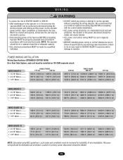
... (1229.9 m) 537 ft. (163.7 m) 807 ft. (246 m) 3228 ft. (983.9 m) ADVERTENCIA 10089 ft. (3075.1 m) 6726 ft. (2050.1 m) 5044 ft. (1537.4 m) IÓN WIRE GAUGE 10 • 1/2 HP Motor ------• 3/4 HP Motor ------• 1 HP Motor --------- 168 ft. (51.2 m) 115 ft. (35.1 m) 84 ft. (25.6 m) ADVERTENCIA 730 ft. (... performed until disconnecting the electrical power and locking-out the power via the operator without consulting the wiring diagram. visible and clearly labeled. • Disconnecting power at that you Install an optional reversing edge BEFORE proceeding with local electrical...
... (1229.9 m) 537 ft. (163.7 m) 807 ft. (246 m) 3228 ft. (983.9 m) ADVERTENCIA 10089 ft. (3075.1 m) 6726 ft. (2050.1 m) 5044 ft. (1537.4 m) IÓN WIRE GAUGE 10 • 1/2 HP Motor ------• 3/4 HP Motor ------• 1 HP Motor --------- 168 ft. (51.2 m) 115 ft. (35.1 m) 84 ft. (25.6 m) ADVERTENCIA 730 ft. (... performed until disconnecting the electrical power and locking-out the power via the operator without consulting the wiring diagram. visible and clearly labeled. • Disconnecting power at that you Install an optional reversing edge BEFORE proceeding with local electrical...

SW490 GL BOARD Manual
Page 16
...sight of the three power leads. Wire control station to electrical wiring diagrams on pages 31-33. Secure all electrical power connections inside the disconnect switch electrical box. Refer to terminals 3 and 5 in the control box on page 15 for correct wire gauges. The operator will function ... • L2 (HOT), BLACK • GROUND, GREEN THREE PHASE All three phase operators will run reversed. WIRING ON/OFF SWITCH POWER WIRING NOTE: Before running power wiring refer to pages 21 and 22. This control will not function unless this situation, shut off power at main power...
...sight of the three power leads. Wire control station to electrical wiring diagrams on pages 31-33. Secure all electrical power connections inside the disconnect switch electrical box. Refer to terminals 3 and 5 in the control box on page 15 for correct wire gauges. The operator will function ... • L2 (HOT), BLACK • GROUND, GREEN THREE PHASE All three phase operators will run reversed. WIRING ON/OFF SWITCH POWER WIRING NOTE: Before running power wiring refer to pages 21 and 22. This control will not function unless this situation, shut off power at main power...

SW490 GL BOARD Manual
Page 31
COMMON DC - IN RPM - SINGLE PHASE WIRING DIAGRAM (SW470) 1 PHASE POWER IN SWITCH NOTE 1 MOTOR GROUND GL CONTROL BOARD J2 PLUG 24 Vac - IN 24 Vac - SEE NOTE 2 R 2 SEE NOTE 4 ALARM ASSY... SIGNAL NOTES: 1) TRANSFORMER PRIMARY VOLTAGE SAME AS OPERATOR LINE VOLTAGE 24V SECONDARY 60VA. 2) TERMINAL DESIGNATIONS SHOWN FOR 115V ONLY. 3) OPTIONAL WIRE HARNESS. 4) (B+) AND (B-) ARE 100dB SAFETY ALARMS. APPLICATIONS: CONTROL WIRING TYPE - GL FIELD WIRING & ADJUSTMENTS MODEL TYPES: HORSEPOWER: VOLTAGE/PHASE: SW470 (MSW) 1/2 115V & 230V, 50/60Hz - 1 PHASE ONLY 845 Larch Avenue, ...
COMMON DC - IN RPM - SINGLE PHASE WIRING DIAGRAM (SW470) 1 PHASE POWER IN SWITCH NOTE 1 MOTOR GROUND GL CONTROL BOARD J2 PLUG 24 Vac - IN 24 Vac - SEE NOTE 2 R 2 SEE NOTE 4 ALARM ASSY... SIGNAL NOTES: 1) TRANSFORMER PRIMARY VOLTAGE SAME AS OPERATOR LINE VOLTAGE 24V SECONDARY 60VA. 2) TERMINAL DESIGNATIONS SHOWN FOR 115V ONLY. 3) OPTIONAL WIRE HARNESS. 4) (B+) AND (B-) ARE 100dB SAFETY ALARMS. APPLICATIONS: CONTROL WIRING TYPE - GL FIELD WIRING & ADJUSTMENTS MODEL TYPES: HORSEPOWER: VOLTAGE/PHASE: SW470 (MSW) 1/2 115V & 230V, 50/60Hz - 1 PHASE ONLY 845 Larch Avenue, ...

SW490 GL BOARD Manual
Page 32
...PRIMARY R1 (BL) 24V Sec. 115 VOLT MOTOR CONNECTION 115 ONLY SEE NOTE 5 (Y) R2 (BK) B- CLOSE 24 Vac - GL FIELD WIRING & ADJUSTMENTS MODEL TYPES: HORSEPOWER: VOLTAGE/PHASE: SW490 (HSW) 1/2, 3/4 & 1 115V, 208 & 230V - 1 PHASE ONLY 845 Larch Avenue, Elmhurst, IL 60125 DRAWING NUMBER: DATE: ... LINE VOLTAGE 24V SECONDARY 60VA. 2) RELAY VOLTAGE SAME AS LINE VOLTAGE. 3) OPTIONAL WIRE HARNESS. 4) (B+) AND (B-) ARE 100dB SAFETY ALARMS. 5) WIRE COLOR: 120V BLACK, 208V RED, 230V ORANGE. SINGLE PHASE WIRING DIAGRAM (SW490) 1 PHASE POWER IN (GN) GROUND (W) (GN) GL CONTROL BOARD 24 Vac...
...PRIMARY R1 (BL) 24V Sec. 115 VOLT MOTOR CONNECTION 115 ONLY SEE NOTE 5 (Y) R2 (BK) B- CLOSE 24 Vac - GL FIELD WIRING & ADJUSTMENTS MODEL TYPES: HORSEPOWER: VOLTAGE/PHASE: SW490 (HSW) 1/2, 3/4 & 1 115V, 208 & 230V - 1 PHASE ONLY 845 Larch Avenue, Elmhurst, IL 60125 DRAWING NUMBER: DATE: ... LINE VOLTAGE 24V SECONDARY 60VA. 2) RELAY VOLTAGE SAME AS LINE VOLTAGE. 3) OPTIONAL WIRE HARNESS. 4) (B+) AND (B-) ARE 100dB SAFETY ALARMS. 5) WIRE COLOR: 120V BLACK, 208V RED, 230V ORANGE. SINGLE PHASE WIRING DIAGRAM (SW490) 1 PHASE POWER IN (GN) GROUND (W) (GN) GL CONTROL BOARD 24 Vac...

SW490 GL BOARD Manual
Page 33
... AN EXTERNAL OVERLOAD. 5) (B+) AND (B-) ARE 100dB SAFETY ALARMS. APPLICATIONS: CONTROL WIRING TYPE - OPEN OBS. THREE PHASE WIRING DIAGRAM (SW490) SEE NOTE 4 ' ' ' ' 3 PHASE POWER IN ON/OFF SWITCH GL CONTROL BOARD 24 Vac - IN RPM - COMMON DC - GL FIELD WIRING & ADJUSTMENTS MODEL TYPES: HORSEPOWER: VOLTAGE/PHASE: SW490 (HSW) 1/2, 3/4 & 1 208,230,460 & 575V - 3 PHASE ONLY DRAWING NUMBER: 01...
... AN EXTERNAL OVERLOAD. 5) (B+) AND (B-) ARE 100dB SAFETY ALARMS. APPLICATIONS: CONTROL WIRING TYPE - OPEN OBS. THREE PHASE WIRING DIAGRAM (SW490) SEE NOTE 4 ' ' ' ' 3 PHASE POWER IN ON/OFF SWITCH GL CONTROL BOARD 24 Vac - IN RPM - COMMON DC - GL FIELD WIRING & ADJUSTMENTS MODEL TYPES: HORSEPOWER: VOLTAGE/PHASE: SW490 (HSW) 1/2, 3/4 & 1 208,230,460 & 575V - 3 PHASE ONLY DRAWING NUMBER: 01...
SW490 GL BOARD Manual
Page 34
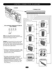
...5 6 7 8 9 10 11 12 13 14 15 16 24 Vac ACCESSORY POWER MAY BE FOUND ON THESE TERMINALS R1 R2 R3 R4 24 Vac NOTE: See wiring diagrams shipped with the gate while operating the controls. Also, always install the controls where the user has full view of gate operation. * All inputs are... strongly recommend that are contrary to operate the gate system, MUST be installed where the user cannot come into contact with kit for wiring distances and wire gauge information. If these instructions are to be used to the advice given here, call for assistance. HARD CLOSE CONTROL INPUT (N.O.) OPEN...
...5 6 7 8 9 10 11 12 13 14 15 16 24 Vac ACCESSORY POWER MAY BE FOUND ON THESE TERMINALS R1 R2 R3 R4 24 Vac NOTE: See wiring diagrams shipped with the gate while operating the controls. Also, always install the controls where the user has full view of gate operation. * All inputs are... strongly recommend that are contrary to operate the gate system, MUST be installed where the user cannot come into contact with kit for wiring distances and wire gauge information. If these instructions are to be used to the advice given here, call for assistance. HARD CLOSE CONTROL INPUT (N.O.) OPEN...

SW490 S3 BOARD Manual
Page 18
Use the electrical wiring diagram supplied with this situation, disconnect power a main power source and at the operator's electrical disconnect switch before proceeding. L1, L2, L3 and ground. To correct ... the operator's electrical disconnect switch. 18 Installation Electrical Power Connections CAUTION Make sure power is properly grounded. Secure all electrical power connections inside the power wiring compartment. All single phase operators will run backwards. If they are phased wrong the gate operator will have -
Use the electrical wiring diagram supplied with this situation, disconnect power a main power source and at the operator's electrical disconnect switch before proceeding. L1, L2, L3 and ground. To correct ... the operator's electrical disconnect switch. 18 Installation Electrical Power Connections CAUTION Make sure power is properly grounded. Secure all electrical power connections inside the power wiring compartment. All single phase operators will run backwards. If they are phased wrong the gate operator will have -

SW490 S3 BOARD Manual
Page 21
...Connections shown here are normally open (constant pressure). Controls and Accessory Installation 21 Controls and Accessory Installation See wiring diagram for wiring distances and wire gauge information. Use safety edges. In any control device. CLOSE 5 10 EXTERNAL ENTRAPMENT CLOSE Will reverse... will not function (disabled). 5 4 CLOSE/SINGLE BUTTON OPEN 5 9 EXTERNAL ENTRAPMENT OPEN Will reverse (close directions. Only wired devices in sight of gate operation. 5 7 SUPERVISED OPEN BUTTON Caution - Loops cannot be ordered factory installed. REQUIRED This ...
...Connections shown here are normally open (constant pressure). Controls and Accessory Installation 21 Controls and Accessory Installation See wiring diagram for wiring distances and wire gauge information. Use safety edges. In any control device. CLOSE 5 10 EXTERNAL ENTRAPMENT CLOSE Will reverse... will not function (disabled). 5 4 CLOSE/SINGLE BUTTON OPEN 5 9 EXTERNAL ENTRAPMENT OPEN Will reverse (close directions. Only wired devices in sight of gate operation. 5 7 SUPERVISED OPEN BUTTON Caution - Loops cannot be ordered factory installed. REQUIRED This ...


