Installation Guide
Page 3
... Sidelobe suppression... 21 To start the radar: 21 RI10 heading source selection: 21 Dual Radar setup: 22 Dual Range setup (Broadband 4GTM Radar only): 23 Maintenance 24 Dimension Drawings 24 Scanner 25 Radar interface box 26 Specifications 26 Broadband 3G™ Radar 27 Broadband 4G™ Radar 28 Navico Broadband radar part numbers 29 RF exposure compliance certificate Contents | Broadband 3G/4G™ Radar Installation Guide | 1
... Sidelobe suppression... 21 To start the radar: 21 RI10 heading source selection: 21 Dual Radar setup: 22 Dual Range setup (Broadband 4GTM Radar only): 23 Maintenance 24 Dimension Drawings 24 Scanner 25 Radar interface box 26 Specifications 26 Broadband 3G™ Radar 27 Broadband 4G™ Radar 28 Navico Broadband radar part numbers 29 RF exposure compliance certificate Contents | Broadband 3G/4G™ Radar Installation Guide | 1

Installation Guide
Page 4
...in accordance with the instructions, may cause harmful interference to the low output power and signal properties. 2 | Contents | Broadband 3G/4G™ Radar Installation Guide Increase the separation between the equipment and receiver. However, there is subject to the following measures: Reorient or relocate ... mW/cm2 . For further compliance information please refer to our websites: http://www.simrad-yachting.com/Products/Marine-Radars http://www.lowrance.com/Products/Marine http://www.bandg.com/Products Industry Canada IC: 4697A-3G4G Operation is no guarantee that may cause...
...in accordance with the instructions, may cause harmful interference to the low output power and signal properties. 2 | Contents | Broadband 3G/4G™ Radar Installation Guide Increase the separation between the equipment and receiver. However, there is subject to the following measures: Reorient or relocate ... mW/cm2 . For further compliance information please refer to our websites: http://www.simrad-yachting.com/Products/Marine-Radars http://www.lowrance.com/Products/Marine http://www.bandg.com/Products Industry Canada IC: 4697A-3G4G Operation is no guarantee that may cause...
Installation Guide
Page 5
... may be translated to specifications without notice. Copyright © 2011 Navico Holding AS. www.lowrance.com www.simrad-yachting.com www.BandG.com Welcome | Broadband 3G/4G™ Radar Installation Guide | 3 Warranty The warranty card is the owner's sole responsibility to install and use the instrument and transducers in this version of this product, we retain...
... may be translated to specifications without notice. Copyright © 2011 Navico Holding AS. www.lowrance.com www.simrad-yachting.com www.BandG.com Welcome | Broadband 3G/4G™ Radar Installation Guide | 3 Warranty The warranty card is the owner's sole responsibility to install and use the instrument and transducers in this version of this product, we retain...

Installation Guide
Page 6
... between the current transmitted frequency and echoed frequency. especially great for a magnetron radar. Frequency 9.41 GHz 9.4 GHz 1ms 5ms Time 4 | Welcome | Broadband 3G/4G™ Radar Installation Guide FMCW radar is different: Firstly it anywhere • Less than a short duration pulse. How does FMCW radar work? 1 Welcome Congratulations on magnetron technology. Secondly, it transmits a 1ms long signal...
... between the current transmitted frequency and echoed frequency. especially great for a magnetron radar. Frequency 9.41 GHz 9.4 GHz 1ms 5ms Time 4 | Welcome | Broadband 3G/4G™ Radar Installation Guide FMCW radar is different: Firstly it anywhere • Less than a short duration pulse. How does FMCW radar work? 1 Welcome Congratulations on magnetron technology. Secondly, it transmits a 1ms long signal...

Installation Guide
Page 7
...collision. • convenience - Meanwhile, the transmitter continues to warm up . No warm up required Short range performance • broadband radar can not see within a few meters of flight to be calculated, from the transmitter retaining the frequency it had when originally ...power • suitable for small boats and yachts • easier installation with lighter cabling and smaller connectors • great for yachts on and use • no constant adjusting required to the receiver, still at all ranges Welcome | Broadband 3G/4G™ Radar Installation Guide | 5
...collision. • convenience - Meanwhile, the transmitter continues to warm up . No warm up required Short range performance • broadband radar can not see within a few meters of flight to be calculated, from the transmitter retaining the frequency it had when originally ...power • suitable for small boats and yachts • easier installation with lighter cabling and smaller connectors • great for yachts on and use • no constant adjusting required to the receiver, still at all ranges Welcome | Broadband 3G/4G™ Radar Installation Guide | 5
Installation Guide
Page 8
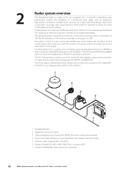
...). Display: Simrad NSO, NSE or NSS / B&G Zeus / Lowrance HDS 7. The 3G kit may be ordered with either interface box, however the Lowrance USA model (00010418-001) is used to connect to 36 nm (target dependent). SimNet or NMEA2000 data network (not included) 6 | Radar system overview | Broadband 3G/4G™ Radar Installation Guide The RI11 interface box is not...
...). Display: Simrad NSO, NSE or NSS / B&G Zeus / Lowrance HDS 7. The 3G kit may be ordered with either interface box, however the Lowrance USA model (00010418-001) is used to connect to 36 nm (target dependent). SimNet or NMEA2000 data network (not included) 6 | Radar system overview | Broadband 3G/4G™ Radar Installation Guide The RI11 interface box is not...

Installation Guide
Page 9
....5 ft) and 30 m (98 ft). If you 'll need a longer cable, consult your radar is factory sealed. DON'T DO THIS! • DON'T install the scanner too high up (eg at any shortcuts! • The Broadband Radar is usually sufficient. Installation | Broadband 3G/4G™ Radar Installation Guide | 7 The ideal location for direct roof mounting" on the position of the...
....5 ft) and 30 m (98 ft). If you 'll need a longer cable, consult your radar is factory sealed. DON'T DO THIS! • DON'T install the scanner too high up (eg at any shortcuts! • The Broadband Radar is usually sufficient. Installation | Broadband 3G/4G™ Radar Installation Guide | 7 The ideal location for direct roof mounting" on the position of the...

Installation Guide
Page 10
... by the hard top. Note: Where the mounting surface is constructed of any time the Broadband Radar is recommended to STBY or OFF any form of metal you must be severely impaired. 8 | Installation | Broadband 3G/4G™ Radar Installation Guide If possible ensure that have a steep planing angle, it is recommended not to mount directly on...
... by the hard top. Note: Where the mounting surface is constructed of any time the Broadband Radar is recommended to STBY or OFF any form of metal you must be severely impaired. 8 | Installation | Broadband 3G/4G™ Radar Installation Guide If possible ensure that have a steep planing angle, it is recommended not to mount directly on...

Installation Guide
Page 11
Installation | Broadband 3G/4G™ Radar Installation Guide | 9 Best performance Broadband Radar 850 mm Hard Top Width For best performance, the radar should be positioned to allow the beams to a vessels hard top overall width. Optimum Performance Elevation of scanner 0.85 m 1.0 m 1.2 m 1.4 m 1.6 m 1.8 m 2.0 m 2.2 m ... is a guide to determine scanner height in relation to clear the superstructure of the boat. Better performance Broadband Radar Above illustrates that raising the Broadband scanner off the hard top allowing most of hard top width over 1.0 m wide: Increase height by...
Installation | Broadband 3G/4G™ Radar Installation Guide | 9 Best performance Broadband Radar 850 mm Hard Top Width For best performance, the radar should be positioned to allow the beams to a vessels hard top overall width. Optimum Performance Elevation of scanner 0.85 m 1.0 m 1.2 m 1.4 m 1.6 m 1.8 m 2.0 m 2.2 m ... is a guide to determine scanner height in relation to clear the superstructure of the boat. Better performance Broadband Radar Above illustrates that raising the Broadband scanner off the hard top allowing most of hard top width over 1.0 m wide: Increase height by...
Installation Guide
Page 12
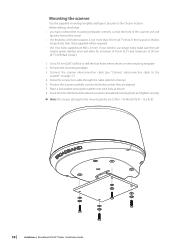
... that they are marine grade stainless steel and allow for the mounting bolts are 12 Nm - 18 Nm (8.9 lb ft - 13.3 lb ft) 10 | Installation | Broadband 3G/4G™ Radar Installation Guide If you have oriented the mounting template correctly so that : • you need to drill the four holes where shown on page 11...
... that they are marine grade stainless steel and allow for the mounting bolts are 12 Nm - 18 Nm (8.9 lb ft - 13.3 lb ft) 10 | Installation | Broadband 3G/4G™ Radar Installation Guide If you have oriented the mounting template correctly so that : • you need to drill the four holes where shown on page 11...

Installation Guide
Page 13
...RJ45 Pin 5 RJ45 Pin 7 RJ45 Pin 8 RJ45 Pin 3 N/A RJ45 Pin 1 RJ45 Pin 6 RJ45 Pin 2 Installation | Broadband 3G/4G™ Radar Installation Guide | 11 Connect interconnection cable to the scanner The scanner interconnection cable connects the scanner to avoid bending the pins....for the scanner end connector • Run the interconnection cable between the scanner and the location of the radar interface box • Insert cable connector on to the male 14 pin plug on to the connectors •...align the connector correctly to the RI10 interface box (or Lowrance HDS via and ethernet adapter cable...
...RJ45 Pin 5 RJ45 Pin 7 RJ45 Pin 8 RJ45 Pin 3 N/A RJ45 Pin 1 RJ45 Pin 6 RJ45 Pin 2 Installation | Broadband 3G/4G™ Radar Installation Guide | 11 Connect interconnection cable to the scanner The scanner interconnection cable connects the scanner to avoid bending the pins....for the scanner end connector • Run the interconnection cable between the scanner and the location of the radar interface box • Insert cable connector on to the male 14 pin plug on to the connectors •...align the connector correctly to the RI10 interface box (or Lowrance HDS via and ethernet adapter cable...

Installation Guide
Page 14
... the interconnection cable to radar interface box To connect interconnection cable to Lowrance HDS (USA only) (see "Connect power" on page 14) A D B FE G C H Data Shield Black Yellow Red 1. Connect RJ45 and phoenix connector to remove the cable gland housing 12 | Installation | Broadband 3G/4G™ Radar Installation Guide Connect data wires to the radar interface box using 5. Secure...
... the interconnection cable to radar interface box To connect interconnection cable to Lowrance HDS (USA only) (see "Connect power" on page 14) A D B FE G C H Data Shield Black Yellow Red 1. Connect RJ45 and phoenix connector to remove the cable gland housing 12 | Installation | Broadband 3G/4G™ Radar Installation Guide Connect data wires to the radar interface box using 5. Secure...

Installation Guide
Page 15
... is unavoidable, use the pin-out below to the surface using the four mounting points and supplied 8G x 5/8 pozi s/s fasters Installation | Broadband 3G/4G™ Radar Installation Guide | 13 RJ45 Connector pinout P8 P1 Pin Color 1 White/Orange 2 Orange 3 White/Green 4 Blue Required to complete ...Brown 8 Brown RJ45 Connector RJ45 Crimping tool Mounting the radar interface box • Install the radar interface box (where applicable) in a dry location away from spray, rain, drips and condensation • The radar interface box must be located where it is not recommended ...
... is unavoidable, use the pin-out below to the surface using the four mounting points and supplied 8G x 5/8 pozi s/s fasters Installation | Broadband 3G/4G™ Radar Installation Guide | 13 RJ45 Connector pinout P8 P1 Pin Color 1 White/Orange 2 Orange 3 White/Green 4 Blue Required to complete ...Brown 8 Brown RJ45 Connector RJ45 Crimping tool Mounting the radar interface box • Install the radar interface box (where applicable) in a dry location away from spray, rain, drips and condensation • The radar interface box must be located where it is not recommended ...

Installation Guide
Page 16
... (Optional) 2 2 4 FUSE FUSE +_ 1. ships with an RI10 interface box, which allows connection of a heading source to the radar 14 | Connect the Broadband radar to your display Lowrance HDS USA (no advantage as they are all shipped with a 10 m (33 ft): Optional 20 m (65 ft) and 30 m... Sensor (see next page) Note: Broadband 4G™ radar may also be connected in this connection is made in 3G™ kit 000- 10418-001 (Lowrance USA only). 4 Connect the Broadband radar to your display | Broadband 3G/4G™ Radar Installation Guide Ethernet adapter cable. 5 pin yellow male ...
... (Optional) 2 2 4 FUSE FUSE +_ 1. ships with an RI10 interface box, which allows connection of a heading source to the radar 14 | Connect the Broadband radar to your display Lowrance HDS USA (no advantage as they are all shipped with a 10 m (33 ft): Optional 20 m (65 ft) and 30 m... Sensor (see next page) Note: Broadband 4G™ radar may also be connected in this connection is made in 3G™ kit 000- 10418-001 (Lowrance USA only). 4 Connect the Broadband radar to your display | Broadband 3G/4G™ Radar Installation Guide Ethernet adapter cable. 5 pin yellow male ...

Installation Guide
Page 17
...: 7. SimNet cable. Ethernet cable (1.8 m (6 ft)). Broadband 3G™ or 4G™ Radar 3. NMEA2000 adapter kit: a) SimNet -Micro-C cable a b 0.5 m (1.6 ft), b) SimNet joiner. The RI10 can connect either directly to your display | Broadband 3G/4G™ Radar Installation Guide c | 15 For cable options see "Ethernet cables" on an LSS-1 Structure scan module. Interconnection cable (Lowrance 10 m (33 ft) Simrad 20...
...: 7. SimNet cable. Ethernet cable (1.8 m (6 ft)). Broadband 3G™ or 4G™ Radar 3. NMEA2000 adapter kit: a) SimNet -Micro-C cable a b 0.5 m (1.6 ft), b) SimNet joiner. The RI10 can connect either directly to your display | Broadband 3G/4G™ Radar Installation Guide c | 15 For cable options see "Ethernet cables" on an LSS-1 Structure scan module. Interconnection cable (Lowrance 10 m (33 ft) Simrad 20...

Installation Guide
Page 18
... a 20 m (65 ft). AT10HD NMEA083 to SimNet Converter Heading Only Cut off 12 Pin plug to your display | Broadband 3G/4G™ Radar Installation Guide Zeus B&G Zeus Simrad NSO, NSE and NSS (SimNet network) 1 B&G Zeus SIMRAD NSO, NSE or NSS MFD 2 3 4 SimNet Ethernet SimNet Ethernet NSO +_ 5 6 FUSE 8 97 10 ...
... a 20 m (65 ft). AT10HD NMEA083 to SimNet Converter Heading Only Cut off 12 Pin plug to your display | Broadband 3G/4G™ Radar Installation Guide Zeus B&G Zeus Simrad NSO, NSE and NSS (SimNet network) 1 B&G Zeus SIMRAD NSO, NSE or NSS MFD 2 3 4 SimNet Ethernet SimNet Ethernet NSO +_ 5 6 FUSE 8 97 10 ...
Installation Guide
Page 19
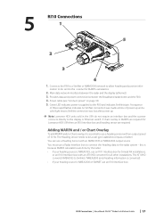
...Lowrance HDS USA then an RI10 Interface box and heading sensor are done by the radar: • If your heading source is supplied to be a rate gyro stabilized compass or better You can use a Radar Interface box to connect the heading data to allow heading and position infor- RI10 Connections | Broadband 3G/4G™ Radar Installation... Guide | 17 this is because MARPA calculations are required Adding MARPA and / or Chart Overlay To add MARPA and/or Chart overlay, it is NMEA0183, use an RI11 Interface box for Simrad NX installations, or...
...Lowrance HDS USA then an RI10 Interface box and heading sensor are done by the radar: • If your heading source is supplied to be a rate gyro stabilized compass or better You can use a Radar Interface box to connect the heading data to allow heading and position infor- RI10 Connections | Broadband 3G/4G™ Radar Installation... Guide | 17 this is because MARPA calculations are required Adding MARPA and / or Chart Overlay To add MARPA and/or Chart overlay, it is NMEA0183, use an RI11 Interface box for Simrad NX installations, or...

Installation Guide
Page 20
...DC (+) BATT (-) For systems not using radar interface box (Lowrance 3G USA only): • Connect the red wire to operate. For systems using the Radar Interface Box make sure all connections have been made to 'Master' under Power Control. 6 ! ! ! Use ignition or install a switch that will draw no power ...is recommended to display Data Red Yellow 5A 12-24 V DC + Black Shield Battery (-) No connect 18 | Connect power | Broadband 3G/4G™ Radar Installation Guide Use a 5 amp fuse or breaker • Connect the yellow wire to power source that will turn on the system (...
...DC (+) BATT (-) For systems not using radar interface box (Lowrance 3G USA only): • Connect the red wire to operate. For systems using the Radar Interface Box make sure all connections have been made to 'Master' under Power Control. 6 ! ! ! Use ignition or install a switch that will draw no power ...is recommended to display Data Red Yellow 5A 12-24 V DC + Black Shield Battery (-) No connect 18 | Connect power | Broadband 3G/4G™ Radar Installation Guide Use a 5 amp fuse or breaker • Connect the yellow wire to power source that will turn on the system (...
Installation Guide
Page 21
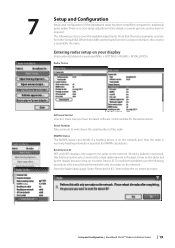
... | Broadband 3G/4G™ Radar Installation Guide | 19 There is essentially the same. The following procedure, which must be detected by pressing MENU > SETTINGS > RADAR > INSTALLATION. Entering radar setup on your display Enter radar installation by the display because it may not be performed with only one radar on the network and that the menu examples used are from the Lowrance...
... | Broadband 3G/4G™ Radar Installation Guide | 19 There is essentially the same. The following procedure, which must be detected by pressing MENU > SETTINGS > RADAR > INSTALLATION. Entering radar setup on your display Enter radar installation by the display because it may not be performed with only one radar on the network and that the menu examples used are from the Lowrance...

Installation Guide
Page 22
...the strongest sidelobe returns are just eliminated. Exit the installation menu 20 | Setup and Configuration | Broadband 3G/4G™ Radar Installation Guide Any inaccuracy will be adjusted. Target loss in all radar systems. The returns caused by experienced radar users. By default this could be seen. The ...increased. Do not set to Auto, and normally should not need to be a large target on the screen with the Broadband radar. Set Radar range to between 1/2nm to 1nm and Sidelobe Suppression to appear as large ships or container ports. Change Auto sidelobe suppression...
...the strongest sidelobe returns are just eliminated. Exit the installation menu 20 | Setup and Configuration | Broadband 3G/4G™ Radar Installation Guide Any inaccuracy will be adjusted. Target loss in all radar systems. The returns caused by experienced radar users. By default this could be seen. The ...increased. Do not set to Auto, and normally should not need to be a large target on the screen with the Broadband radar. Set Radar range to between 1/2nm to 1nm and Sidelobe Suppression to appear as large ships or container ports. Change Auto sidelobe suppression...


