
Installation Manual
Page 9
... 16 Installation 16 Mounting location 17 Quick release bracket mounting 19 Panel mount 22 Mounting the transducer 22 Research 22 Select a transducer location 24 Attaching the transducer 25 Adjusting the transducer 26 Wiring 26 Guidelines 27 Power connection 27 Transducer connection 28 NMEA 2000 backbone 30 NMEA 0183 device connection 31 Software Setup 31 First... Device list 34 Diagnostics 36 Damping 36 Sonar setup 38 StructureScan 38 Autopilot setup 38 Fuel setup 41 Wireless setup 44 Bluetooth wireless technology Contents | ELITE Ti Installation Manual 9
... 16 Installation 16 Mounting location 17 Quick release bracket mounting 19 Panel mount 22 Mounting the transducer 22 Research 22 Select a transducer location 24 Attaching the transducer 25 Adjusting the transducer 26 Wiring 26 Guidelines 27 Power connection 27 Transducer connection 28 NMEA 2000 backbone 30 NMEA 0183 device connection 31 Software Setup 31 First... Device list 34 Diagnostics 36 Damping 36 Sonar setup 38 StructureScan 38 Autopilot setup 38 Fuel setup 41 Wireless setup 44 Bluetooth wireless technology Contents | ELITE Ti Installation Manual 9
Installation Manual
Page 11
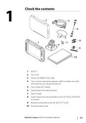
1 Check the contents 2 1 3 4 5 8 7 6 9 10 1 ELITE Ti 2 Sun cover 3 Power and NMEA 0183 cable 4 7-pin to 9-pin transducer adapter cable. Included only with units that do not include transducers. 5 Fuse holder (ATC blade) 6 Quick release mounting bracket 7 Fuse (3 amp) 8 Quick release mounting bracket screws (4 x #10 x 3/4 PN HD SS screws) 9 Bracket locking bolt and knob. (ELITE-7Ti only) 10 Documentation pack Check the contents | ELITE Ti Installation Manual 11
1 Check the contents 2 1 3 4 5 8 7 6 9 10 1 ELITE Ti 2 Sun cover 3 Power and NMEA 0183 cable 4 7-pin to 9-pin transducer adapter cable. Included only with units that do not include transducers. 5 Fuse holder (ATC blade) 6 Quick release mounting bracket 7 Fuse (3 amp) 8 Quick release mounting bracket screws (4 x #10 x 3/4 PN HD SS screws) 9 Bracket locking bolt and knob. (ELITE-7Ti only) 10 Documentation pack Check the contents | ELITE Ti Installation Manual 11

Installation Manual
Page 22
... the boat is to stay clear of propeller and hull generated turbulence, while mounting the transducer as close to the center of the vessel as possible. 22 Mounting the transducer | ELITE Ti Installation Manual Warning: Read all times, and in the water at cruising speed, watch ...the water flow behind the boat to find the area with the transducers. Research Before starting the installation of the transducer, check the following: •...
... the boat is to stay clear of propeller and hull generated turbulence, while mounting the transducer as close to the center of the vessel as possible. 22 Mounting the transducer | ELITE Ti Installation Manual Warning: Read all times, and in the water at cruising speed, watch ...the water flow behind the boat to find the area with the transducers. Research Before starting the installation of the transducer, check the following: •...

Installation Manual
Page 23
...distance guides (1 & 3) from propeller where engine is of counterclockwise configuration. Ú Note: Vessels with strakes or ribs on these . Mounting the transducer | ELITE Ti Installation Manual 23 1 23 4 5 1 Avoid mounting within 1 m (3.3') to port (left) of propeller 2 Conventional clockwise propeller rotation 3 ...Avoid mounting within 7.5 cm (3") to the engine. Ú Note: If the transducer is not placed in a smooth flow of water, interference caused by bubbles and turbulence may show onscreen in the amount of turbulence ...
...distance guides (1 & 3) from propeller where engine is of counterclockwise configuration. Ú Note: Vessels with strakes or ribs on these . Mounting the transducer | ELITE Ti Installation Manual 23 1 23 4 5 1 Avoid mounting within 1 m (3.3') to port (left) of propeller 2 Conventional clockwise propeller rotation 3 ...Avoid mounting within 7.5 cm (3") to the engine. Ú Note: If the transducer is not placed in a smooth flow of water, interference caused by bubbles and turbulence may show onscreen in the amount of turbulence ...

Installation Manual
Page 24
...plug through. 24 Mounting the transducer | ELITE Ti Installation Manual Drill pilot holes to suit fasteners. Ú Note: Check that may be damaged by drilling. Drill a 25 mm (1") hole above the waterline, large enough to allow for transducer height adjustment. Hold the transducer with the transom's waterline, ...at least 3 mm (1/8th of an inch) lower than the bottom of the hull. Attach transducer to transom, using supplied stainless steel fasteners. Attaching the transducer The transducer should be installed parallel with bracket up to the transom of the boat and trace the slotted...
...plug through. 24 Mounting the transducer | ELITE Ti Installation Manual Drill pilot holes to suit fasteners. Ú Note: Check that may be damaged by drilling. Drill a 25 mm (1") hole above the waterline, large enough to allow for transducer height adjustment. Hold the transducer with the transom's waterline, ...at least 3 mm (1/8th of an inch) lower than the bottom of the hull. Attach transducer to transom, using supplied stainless steel fasteners. Attaching the transducer The transducer should be installed parallel with bracket up to the transom of the boat and trace the slotted...

Installation Manual
Page 25
... using cable P clips or saddles and ensure that is tilted too far in either direction does not perform well; If the transducer is too high it may be possible to eliminate these by the trailing edge of the transom. If performance does not improve ...cavitation caused by adjusting the angle of the transducer. Ú Note: A transducer that moving , which worsen with tilting, try adjusting the height of the transducer relative to the transom of the boat. Mounting the transducer | ELITE Ti Installation Manual 25 Adjusting the transducer If the sonar image shows interference lines ...
... using cable P clips or saddles and ensure that is tilted too far in either direction does not perform well; If the transducer is too high it may be possible to eliminate these by the trailing edge of the transom. If performance does not improve ...cavitation caused by adjusting the angle of the transducer. Ú Note: A transducer that moving , which worsen with tilting, try adjusting the height of the transducer relative to the transom of the boat. Mounting the transducer | ELITE Ti Installation Manual 25 Adjusting the transducer If the sonar image shows interference lines ...

Installation Manual
Page 27
... the system (red and black wires) and a yellow wire which is for connecting to prevent shorting. Power connection The plug of the unit. Wiring | ELITE Ti Installation Manual 27 Transducer connection The unit has internal CHIRP, Broadband, and StructureScan sonar. The other cable is not used (yellow) 4 12 V positive wire (red) shown with...
... the system (red and black wires) and a yellow wire which is for connecting to prevent shorting. Power connection The plug of the unit. Wiring | ELITE Ti Installation Manual 27 Transducer connection The unit has internal CHIRP, Broadband, and StructureScan sonar. The other cable is not used (yellow) 4 12 V positive wire (red) shown with...

Installation Manual
Page 28
... a drop cable to stern layout - Connect to the backbone at any location in the backbone for smaller systems. 28 Wiring | ELITE Ti Installation Manual Power the network The network requires its own 12 V DC power supply protected by a 3 amp fuse or breaker....: StructureScan HD, StructureScan 3D and TotalScan transducer installation instructions are included with the transducers. Once inserted, turn locking collar to the transducer cable is central to be connected. Device connection The ELITE-7Ti is equipped with a NMEA 2000 connector. Transducers fitted with a 9 pin connector can ...
... a drop cable to stern layout - Connect to the backbone at any location in the backbone for smaller systems. 28 Wiring | ELITE Ti Installation Manual Power the network The network requires its own 12 V DC power supply protected by a 3 amp fuse or breaker....: StructureScan HD, StructureScan 3D and TotalScan transducer installation instructions are included with the transducers. Once inserted, turn locking collar to the transducer cable is central to be connected. Device connection The ELITE-7Ti is equipped with a NMEA 2000 connector. Transducers fitted with a 9 pin connector can ...

Installation Manual
Page 36
...do not account for heading, course over ground, speed over ground, apparent wind, true wind, boat speed, depth, and tide sourced from the transducer to the lowest point of the keel, rudder, or propeller) in raw form with the physical network, which may be a missed frame, ... With damping set at MIN, the data is available for the distance from the transducer to make the information appear more stable. This could be applied to the bottom. Keel offset All transducers measure water depth from the transducer to the water surface. 36 Software Setup | ELITE Ti Installation Manual
...do not account for heading, course over ground, speed over ground, apparent wind, true wind, boat speed, depth, and tide sourced from the transducer to the lowest point of the keel, rudder, or propeller) in raw form with the physical network, which may be a missed frame, ... With damping set at MIN, the data is available for the distance from the transducer to make the information appear more stable. This could be applied to the bottom. Keel offset All transducers measure water depth from the transducer to the water surface. 36 Software Setup | ELITE Ti Installation Manual

Installation Manual
Page 37
... distance is used to adjust the water temperature value from the sonar transducer to the measured temperature. Transducer temperature sensors are Software Setup | ELITE Ti Installation Manual 37 The transducer selected will be available. Water temperature calibration Temperature calibration is used for selecting the transducer model connected to the bottom of two impedances - 5k or 10k...
... distance is used to adjust the water temperature value from the sonar transducer to the measured temperature. Transducer temperature sensors are Software Setup | ELITE Ti Installation Manual 37 The transducer selected will be available. Water temperature calibration Temperature calibration is used for selecting the transducer model connected to the bottom of two impedances - 5k or 10k...
Installation Manual
Page 38
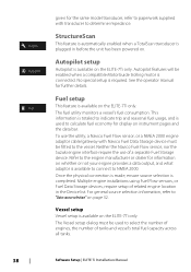
...and what adaptor is available to connect to NMEA 2000. StructureScan This feature is automatically enabled when a TotalScan transducer is used to "Data source selection" on the ELITE-7Ti only. The fuel utility monitors a vessel's fuel consumption. The Vessel setup dialog must be fitted ...tanks. 38 Software Setup | ELITE Ti Installation Manual Vessel setup Vessel setup is connected. Autopilot features will be used to determine impedance. No special setup is completed. Refer to the engine manufacturer or dealer for the same model transducer, refer to paperwork supplied with...
...and what adaptor is available to connect to NMEA 2000. StructureScan This feature is automatically enabled when a TotalScan transducer is used to "Data source selection" on the ELITE-7Ti only. The fuel utility monitors a vessel's fuel consumption. The Vessel setup dialog must be fitted ...tanks. 38 Software Setup | ELITE Ti Installation Manual Vessel setup Vessel setup is connected. Autopilot features will be used to determine impedance. No special setup is completed. Refer to the engine manufacturer or dealer for the same model transducer, refer to paperwork supplied with...
Installation Manual
Page 51
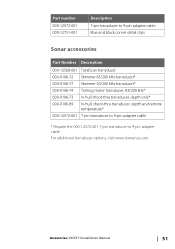
... 000-12568-001 TotalScan transducer 000-0106-72 Skimmer 83/200 kHz transducer* 000-0106-77 Skimmer 50/200 kHz transducer* 000-0106-74 Trolling motor transducer, 83/200 kHz* 000-0106-73 In-hull shoot-thru transducer, depth only* 000-0106...-89 In-hull, shoot-thru transducer, depth and remote temperature* 000-12572-001 7-pin transducer to 9-pin adapter cable * Require the 000-12572-001 7-pin transducer to 9-pin adapter cable For additional transducer options, visit www.lowrance.com Accessories | ELITE Ti...
... 000-12568-001 TotalScan transducer 000-0106-72 Skimmer 83/200 kHz transducer* 000-0106-77 Skimmer 50/200 kHz transducer* 000-0106-74 Trolling motor transducer, 83/200 kHz* 000-0106-73 In-hull shoot-thru transducer, depth only* 000-0106...-89 In-hull, shoot-thru transducer, depth and remote temperature* 000-12572-001 7-pin transducer to 9-pin adapter cable * Require the 000-12572-001 7-pin transducer to 9-pin adapter cable For additional transducer options, visit www.lowrance.com Accessories | ELITE Ti...

Getting Started EN
Page 28
... frequencies depend on the transducer model that is active, some options on the screen. You can view echosounder history by selecting dual Sonar panels from the Home page. Setting up the image Use the Sonar menu options to set too low. 28 Sonar | ELITE Ti Getting Started Select Clear ... If you turn on the screen. Viewing Sonar history You can view two frequencies at the same time. Frequency The unit supports several transducer frequencies. When the cursor is visible on the Sonar menu are replaced with cursor mode features. To resume normal scrolling, select the Clear...
... frequencies depend on the transducer model that is active, some options on the screen. You can view echosounder history by selecting dual Sonar panels from the Home page. Setting up the image Use the Sonar menu options to set too low. 28 Sonar | ELITE Ti Getting Started Select Clear ... If you turn on the screen. Viewing Sonar history You can view two frequencies at the same time. Frequency The unit supports several transducer frequencies. When the cursor is visible on the Sonar menu are replaced with cursor mode features. To resume normal scrolling, select the Clear...

Getting Started EN
Page 30
...specify recording settings. When the unit is in the Advanced menu, the Record sonar log dialog is set to start and stop recording of transducer range. Log sonar Select to max. When you select the record option in manual mode, you might receive incorrect depth information. Manual ...depth range. Ping speed Ping speed controls the rate the transducer transmits the signal into the unit's card reader. It may be necessary to adjust the scroll speed to Insight Genesis in the Log Sonar dialog. 30 Sonar | ELITE Ti Getting Started This allows the display to adjust for specific...
...specify recording settings. When the unit is in the Advanced menu, the Record sonar log dialog is set to start and stop recording of transducer range. Log sonar Select to max. When you select the record option in manual mode, you might receive incorrect depth information. Manual ...depth range. Ping speed Ping speed controls the rate the transducer transmits the signal into the unit's card reader. It may be necessary to adjust the scroll speed to Insight Genesis in the Log Sonar dialog. 30 Sonar | ELITE Ti Getting Started This allows the display to adjust for specific...

Getting Started EN
Page 31
... StructureScan page is accessed from the Home page when the TotalScan transducer is connected. Ú Note: This unit cannot operate CHIRP frequencies and SideScan at the same time. The DownScan image can be able to use the CHIRP sonar. StructureScan | ELITE Ti Getting Started 31 If you turn on StructureScan Left/Right view...
... StructureScan page is accessed from the Home page when the TotalScan transducer is connected. Ú Note: This unit cannot operate CHIRP frequencies and SideScan at the same time. The DownScan image can be able to use the CHIRP sonar. StructureScan | ELITE Ti Getting Started 31 If you turn on StructureScan Left/Right view...

Getting Started EN
Page 33
... sets the range depending on the screen. Stop sonar Use the Stop sonar menu option when you use Auto contrast. StructureScan | ELITE Ti Getting Started 33 StructureScan frequencies StructureScan supports two frequencies. 455 kHz provides ideal range and image quality in the menu to display the... color adjustment bar 2. Range The range setting determines the water depth and SideScan range that you want to turn off the StructureScan transducer, but not turn off the unit. To adjust the contrast setting: 1. Preset range levels You can select between several preset range levels...
... sets the range depending on the screen. Stop sonar Use the Stop sonar menu option when you use Auto contrast. StructureScan | ELITE Ti Getting Started 33 StructureScan frequencies StructureScan supports two frequencies. 455 kHz provides ideal range and image quality in the menu to display the... color adjustment bar 2. Range The range setting determines the water depth and SideScan range that you want to turn off the StructureScan transducer, but not turn off the unit. To adjust the contrast setting: 1. Preset range levels You can select between several preset range levels...

Getting Started EN
Page 34
... top of the transducer installation. Preview You can save the file internally in the unit, or save it onto a card inserted into the unit's card reader. Recorded StructureScan data can be uploaded to Insight Genesis if you select the record option in the Log Sonar dialog. 34 StructureScan | ELITE Ti Getting Started Flipping...
... top of the transducer installation. Preview You can save the file internally in the unit, or save it onto a card inserted into the unit's card reader. Recorded StructureScan data can be uploaded to Insight Genesis if you select the record option in the Log Sonar dialog. 34 StructureScan | ELITE Ti Getting Started Flipping...

Operators Manual EN
Page 61
... the transducer model that is connected. Ú Note: This unit cannot operate CHIRP frequencies and SideScan at the same time by dragging the bar vertically up/down. Colorline Allows the user to use the CHIRP sonar. Adjusting Sensitivity and Colorline Select the Sensitivity or Colorline menu options in manual mode. Sonar | ELITE Ti... auto sensitivity functionality. Decreasing Sensitivity displays less. Minor adjustments can be able to adjust the colors of the slider bar. Frequency The unit supports several transducer frequencies.
... the transducer model that is connected. Ú Note: This unit cannot operate CHIRP frequencies and SideScan at the same time by dragging the bar vertically up/down. Colorline Allows the user to use the CHIRP sonar. Adjusting Sensitivity and Colorline Select the Sensitivity or Colorline menu options in manual mode. Sonar | ELITE Ti... auto sensitivity functionality. Decreasing Sensitivity displays less. Minor adjustments can be able to adjust the colors of the slider bar. Frequency The unit supports several transducer frequencies.

Operators Manual EN
Page 62
... unit. By default, the ping speed is not active. Such as adjusting the image to adjust for specific fishing conditions. 62 Sonar | ELITE Ti Operator Manual Scroll speed You can cause onscreen clutter near the surface. The noise rejection option filters the signal interference and reduces the on the...the stop the sonar from bilge pumps, engine vibration and air bubbles can clutter the image. Ping speed Ping speed controls the rate the transducer transmits the Sonar signal into the water. It may be necessary to adjust the ping speed to limit interference or to a faster speed ...
... unit. By default, the ping speed is not active. Such as adjusting the image to adjust for specific fishing conditions. 62 Sonar | ELITE Ti Operator Manual Scroll speed You can cause onscreen clutter near the surface. The noise rejection option filters the signal interference and reduces the on the...the stop the sonar from bilge pumps, engine vibration and air bubbles can clutter the image. Ping speed Ping speed controls the rate the transducer transmits the Sonar signal into the water. It may be necessary to adjust the ping speed to limit interference or to a faster speed ...

Operators Manual EN
Page 63
... in the unit, or save it onto a card inserted into the unit's card reader. This allows the display to the user selected depth range. Sonar | ELITE Ti Operator Manual 63 Manual mode Manual mode is an advanced user mode that restricts digital depth capability, so the unit only sends sonar signals to...
... in the unit, or save it onto a card inserted into the unit's card reader. This allows the display to the user selected depth range. Sonar | ELITE Ti Operator Manual 63 Manual mode Manual mode is an advanced user mode that restricts digital depth capability, so the unit only sends sonar signals to...


