
Installation Manual
Page 1
HDS Gen2 Touch Installation Manual ENGLISH lowrance.com
HDS Gen2 Touch Installation Manual ENGLISH lowrance.com

Installation Manual
Page 3
...: www.lowrance.com Declarations and conformance This equipment is intended for observing safe boating practices. It is the owner's sole responsibility to install and use in international waters as well as inland waters and coastal sea areas administered by countries of the manual. The ...THAT MAY CAUSE ACCIDENTS, DAMAGE OR THAT MAY VIOLATE THE LAW. and E.E.A. | 1 In the event of any conflict between any instruction manuals, user guides and other information relating to the product (Documentation) may not be translated to, or has been translated from, another language (...
...: www.lowrance.com Declarations and conformance This equipment is intended for observing safe boating practices. It is the owner's sole responsibility to install and use in international waters as well as inland waters and coastal sea areas administered by countries of the manual. The ...THAT MAY CAUSE ACCIDENTS, DAMAGE OR THAT MAY VIOLATE THE LAW. and E.E.A. | 1 In the event of any conflict between any instruction manuals, user guides and other information relating to the product (Documentation) may not be translated to, or has been translated from, another language (...

Installation Manual
Page 5
.../Support/Library/ Important text that they should proceed carefully to warn personnel that requires special attention from the reader is a reference guide for installing the Lowrance HDS-7, HDS-9, and HDS-12 Gen2 Touch system. Warning: Used when it is necessary to prevent risk of Navico. | 3 About this manual This manual is emphasized as radars, echo sounders and AIS work.
.../Support/Library/ Important text that they should proceed carefully to warn personnel that requires special attention from the reader is a reference guide for installing the Lowrance HDS-7, HDS-9, and HDS-12 Gen2 Touch system. Warning: Used when it is necessary to prevent risk of Navico. | 3 About this manual This manual is emphasized as radars, echo sounders and AIS work.

Installation Manual
Page 8
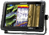
... at around 12V, but due to the dash. Power should be mounted on 10.8 V - 17 V. 6 | HDS Gen2 Touch overview | HDS Gen2 Touch Installation Manual The ability to network over NMEA 2000 and ethernet allows access to data as well as control of boat power systems, the... in GPS receiver and Insight cartography (region dependent) and with optional Navionics support via an SD card slot. 1 HDS Gen2 Touch overview The HDS-7, HDS-9, and HDS-12 Gen2 Touch multifunction displays are charting ready, with built-in to the variable nature of numerous optional devices that can provide sonar...
... at around 12V, but due to the dash. Power should be mounted on 10.8 V - 17 V. 6 | HDS Gen2 Touch overview | HDS Gen2 Touch Installation Manual The ability to network over NMEA 2000 and ethernet allows access to data as well as control of boat power systems, the... in GPS receiver and Insight cartography (region dependent) and with optional Navionics support via an SD card slot. 1 HDS Gen2 Touch overview The HDS-7, HDS-9, and HDS-12 Gen2 Touch multifunction displays are charting ready, with built-in to the variable nature of numerous optional devices that can provide sonar...

Installation Manual
Page 9
controls 1 3 4 2 5 6 1 Touchscreen 2 Card reader door 3 Pages key 4 Zoom in / Zoom out key 5 Mark / Waypoint key 6 Power key HDS Gen2 Touch overview | HDS Gen2 Touch Installation Manual | 7 Front -
controls 1 3 4 2 5 6 1 Touchscreen 2 Card reader door 3 Pages key 4 Zoom in / Zoom out key 5 Mark / Waypoint key 6 Power key HDS Gen2 Touch overview | HDS Gen2 Touch Installation Manual | 7 Front -
Installation Manual
Page 10
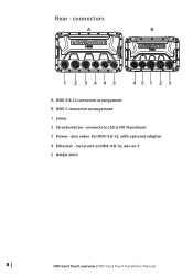
connects to LSS-2 HD Transducer 3 Power - also video for HDS-9 & 12, with optional adaptor 4 Ethernet - two ports on HDS-9 & 12, one on 7 5 NMEA 2000 8 | HDS Gen2 Touch overview | HDS Gen2 Touch Installation Manual connectors A B 1 2 3445 451 2 3 A HDS-9 & 12 connector arrangement B HDS-7 connector arrangement 1 Sonar 2 StructureScan - Rear -
connects to LSS-2 HD Transducer 3 Power - also video for HDS-9 & 12, with optional adaptor 4 Ethernet - two ports on HDS-9 & 12, one on 7 5 NMEA 2000 8 | HDS Gen2 Touch overview | HDS Gen2 Touch Installation Manual connectors A B 1 2 3445 451 2 3 A HDS-9 & 12 connector arrangement B HDS-7 connector arrangement 1 Sonar 2 StructureScan - Rear -

Installation Manual
Page 11
HDS Gen2 Touch overview | HDS Gen2 Touch Installation Manual | 9 The card reader door should always be shut immediately after inserting or removing a card, in order to the left, then pulling forward from the left side. The card reader door is opened by lightly pressing and sliding the door to prevent possible water ingress. ¼¼ Note: The HDS-9 and 12 Displays have two card readers, the HDS-7 has one. SD card slot Used for optional Navionics or InsightHD chart data, software updates, transfer of user data and system backup.
HDS Gen2 Touch overview | HDS Gen2 Touch Installation Manual | 9 The card reader door should always be shut immediately after inserting or removing a card, in order to the left, then pulling forward from the left side. The card reader door is opened by lightly pressing and sliding the door to prevent possible water ingress. ¼¼ Note: The HDS-9 and 12 Displays have two card readers, the HDS-7 has one. SD card slot Used for optional Navionics or InsightHD chart data, software updates, transfer of user data and system backup.

Installation Manual
Page 12
manuals 10 | Check the contents | HDS Gen2 Touch Installation Manual 2 Check the contents Display Bracket knobs (x2) Front Bezel (attached to unit) Power cable Sun cover Fasteners - #6 x 1.5" (4x) Mounting bracket Parts Included, dependent on model 83/200 KHz transducer LSS-2 HD transducer 50/200 KHz transducer DVD -
manuals 10 | Check the contents | HDS Gen2 Touch Installation Manual 2 Check the contents Display Bracket knobs (x2) Front Bezel (attached to unit) Power cable Sun cover Fasteners - #6 x 1.5" (4x) Mounting bracket Parts Included, dependent on model 83/200 KHz transducer LSS-2 HD transducer 50/200 KHz transducer DVD -

Installation Manual
Page 13
...cut . Test the unit in direct sunlight, but for all relevant cables. Leave sufficient clearance to overheat. Lowrance displays are no hidden electrical wires or other parts behind the panel. Ensure that the operator can cast ...off dangerous protectiles. For overall width and height requirements, please see the display screen. Lowrance displays are high-contrast and anti-reflective, and are in doubt, consult a qualified boat builder. If in ... submerged, or where it might be used , eg. Display Installation | HDS Gen2 Touch Installation Manual | 11
...cut . Test the unit in direct sunlight, but for all relevant cables. Leave sufficient clearance to overheat. Lowrance displays are no hidden electrical wires or other parts behind the panel. Ensure that the operator can cast ...off dangerous protectiles. For overall width and height requirements, please see the display screen. Lowrance displays are high-contrast and anti-reflective, and are in doubt, consult a qualified boat builder. If in ... submerged, or where it might be used , eg. Display Installation | HDS Gen2 Touch Installation Manual | 11
Installation Manual
Page 14
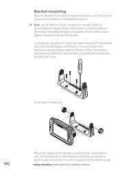
.... If the material is required on both sides to allow tightening and loosening of the display. Screw down the bracket. 12 | Mount the display to the mounting surface material. Display Installation | HDS Gen2 Touch Installation Manual Bracket mounting Place the bracket in the desired mounting location, and use a pencil or permanent marker to mark drilling...
.... If the material is required on both sides to allow tightening and loosening of the display. Screw down the bracket. 12 | Mount the display to the mounting surface material. Display Installation | HDS Gen2 Touch Installation Manual Bracket mounting Place the bracket in the desired mounting location, and use a pencil or permanent marker to mark drilling...
Installation Manual
Page 15
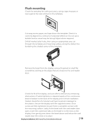
... bead of sealant to the back of a 'neutral cure' type to prevent damage to final installation. Sealant should be listing! Display Installation | HDS Gen2 Touch Installation Manual | 13 Check it clicks in to the slots on the template. 95.3 mm (7.50") MOUNTING SCREW SIZE IS #6 TAPPING SCREW CL 110.2... mm (3.75") 99.5 mm (3.92") 95.3 mm (7.50") PRODUCSTUNOUCTOLVINEER 190.5 mm (7.50") 199.0 mm (7.83") 220.4 mm (8.68") Check dimensions before cutting 12...
... bead of sealant to the back of a 'neutral cure' type to prevent damage to final installation. Sealant should be listing! Display Installation | HDS Gen2 Touch Installation Manual | 13 Check it clicks in to the slots on the template. 95.3 mm (7.50") MOUNTING SCREW SIZE IS #6 TAPPING SCREW CL 110.2... mm (3.75") 99.5 mm (3.92") 95.3 mm (7.50") PRODUCSTUNOUCTOLVINEER 190.5 mm (7.50") 199.0 mm (7.83") 220.4 mm (8.68") Check dimensions before cutting 12...

Installation Manual
Page 16
... configuration. avoid mounting behind here ¼¼ Note: Reverse the distance guides (1 & 3) from propeller where engine is of propeller 4 Best mounting location - Display Installation | HDS Gen2 Touch Installation Manual undisturbed water flow 5 Planing strake - To function properly the transducer must be in the water at cruising speed to determine the area of transom with...
... configuration. avoid mounting behind here ¼¼ Note: Reverse the distance guides (1 & 3) from propeller where engine is of propeller 4 Best mounting location - Display Installation | HDS Gen2 Touch Installation Manual undisturbed water flow 5 Planing strake - To function properly the transducer must be in the water at cruising speed to determine the area of transom with...

Installation Manual
Page 17
.... Attach transducer to pass the plug through. Drill a 25mm (1") hole above the waterline, large enough to transom, using supplied stainless steel fasteners. Display Installation | HDS Gen2 Touch Installation Manual | 15 Drill pilot holes to the engine. ¼¼ Note: If the transducer is nothing on plane. ¼¼ Note: Trim tabs will vary in...
.... Attach transducer to pass the plug through. Drill a 25mm (1") hole above the waterline, large enough to transom, using supplied stainless steel fasteners. Display Installation | HDS Gen2 Touch Installation Manual | 15 Drill pilot holes to the engine. ¼¼ Note: If the transducer is nothing on plane. ¼¼ Note: Trim tabs will vary in...

Installation Manual
Page 18
... and ensure that moving , which worsen with tilting, try adjusting the height of the transducer relative to the transom of the transom. 16 | Display Installation | HDS Gen2 Touch Installation Manual Secure the cable to the hull at speed.
... and ensure that moving , which worsen with tilting, try adjusting the height of the transducer relative to the transom of the transom. 16 | Display Installation | HDS Gen2 Touch Installation Manual Secure the cable to the hull at speed.
Installation Manual
Page 19
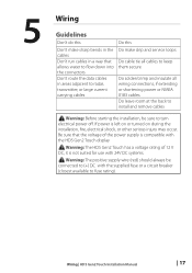
...bends in the cables Don't run cables in a way that the voltage of 12 V DC, it is not suited for use with the supplied fuse or a circuit breaker (closest available to fuse rating). Wiring | HDS Gen2 Touch Installation Manual | 17 Warning: Before starting the installation, be connected to (+) DC with 24V...connections, if extending or shortening power or NMEA 0183 cables Do leave room at the back to install and remove cables ! Warning: The HDS Gen2 Touch has a voltage rating of the power supply is left on or turned on during the installation, fire, electrical shock, or other serious ...
...bends in the cables Don't run cables in a way that the voltage of 12 V DC, it is not suited for use with the supplied fuse or a circuit breaker (closest available to fuse rating). Wiring | HDS Gen2 Touch Installation Manual | 17 Warning: Before starting the installation, be connected to (+) DC with 24V...connections, if extending or shortening power or NMEA 0183 cables Do leave room at the back to install and remove cables ! Warning: The HDS Gen2 Touch has a voltage rating of the power supply is left on or turned on during the installation, fire, electrical shock, or other serious ...
Installation Manual
Page 20
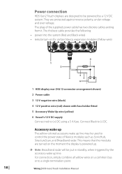
...Yellow wire) 18 | 4 1 2 3 5 6 _+ 1 HDS display rear (9 & 12 connector arrangement shown) 2 Power cable 3 12 V negative wire (black) 4 12 V positive wire (red) shown with fuse holder fitted 5 Accessory Wake Up wire (yellow) 6 Vessel's 12 V DC supply Connect red to a single termination point. For ...has two discrete cables exiting from it. Power connection HDS Gen2 Touch displays are designed to (-) DC. Connect Black to be put in standby, when triggered by a 12 V DC system. Wiring | HDS Gen2 Touch Installation Manual The plug of Navico modules such as SonicHub, StructureScan,...
...Yellow wire) 18 | 4 1 2 3 5 6 _+ 1 HDS display rear (9 & 12 connector arrangement shown) 2 Power cable 3 12 V negative wire (black) 4 12 V positive wire (red) shown with fuse holder fitted 5 Accessory Wake Up wire (yellow) 6 Vessel's 12 V DC supply Connect red to a single termination point. For ...has two discrete cables exiting from it. Power connection HDS Gen2 Touch displays are designed to (-) DC. Connect Black to be put in standby, when triggered by a 12 V DC system. Wiring | HDS Gen2 Touch Installation Manual The plug of Navico modules such as SonicHub, StructureScan,...
Installation Manual
Page 21
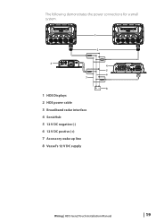
The following demonstrates the power connections for a small system. 1 2 3 7 1 HDS Displays 2 HDS power cable 3 Broadband radar interface 4 SonicHub 5 12 V DC negative (-) 6 12 V DC postive (+) 7 Accessory wake up line 8 Vessel's 12 V DC supply 4 5 6 +_ 8 Wiring | HDS Gen2 Touch Installation Manual | 19
The following demonstrates the power connections for a small system. 1 2 3 7 1 HDS Displays 2 HDS power cable 3 Broadband radar interface 4 SonicHub 5 12 V DC negative (-) 6 12 V DC postive (+) 7 Accessory wake up line 8 Vessel's 12 V DC supply 4 5 6 +_ 8 Wiring | HDS Gen2 Touch Installation Manual | 19
Installation Manual
Page 22
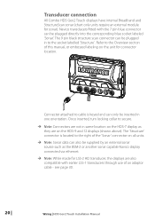
.... ¼¼ Note: While made for connector location. see page 30. 20 | Wiring | HDS Gen2 Touch Installation Manual Refer to the socket labelled 'Structure' . Navico transducers fitted with earlier LSS-1 transducers through use of this manual, or embossed labeling on the HDS-9 and 12 displays (shown above). The 9 pin black structure scan connector can be inserted in...
.... ¼¼ Note: While made for connector location. see page 30. 20 | Wiring | HDS Gen2 Touch Installation Manual Refer to the socket labelled 'Structure' . Navico transducers fitted with earlier LSS-1 transducers through use of this manual, or embossed labeling on the HDS-9 and 12 displays (shown above). The 9 pin black structure scan connector can be inserted in...
Installation Manual
Page 23
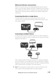
...optional network expansion Port (NEP-2). The HDS-7 display has one ethernet device to a HDS-7 display, or two devices to provide the required ports. Connecting to multiple devices If connecting more NEP-2 modules together to a HDS-9 or HDS-12 display, use of available ports on...link two or more than one ethernet port, whereas the HDS-9 and 12 displays have a locking collar, for maintaining a reliable, waterproof connection. The NEP-2 modules are fitted with 5 ethernet ports. Wiring | HDS Gen2 Touch Installation Manual | 21 Ethernet device connection Ethernet is used for linking ...
...optional network expansion Port (NEP-2). The HDS-7 display has one ethernet device to a HDS-7 display, or two devices to provide the required ports. Connecting to multiple devices If connecting more NEP-2 modules together to a HDS-9 or HDS-12 display, use of available ports on...link two or more than one ethernet port, whereas the HDS-9 and 12 displays have a locking collar, for maintaining a reliable, waterproof connection. The NEP-2 modules are fitted with 5 ethernet ports. Wiring | HDS Gen2 Touch Installation Manual | 21 Ethernet device connection Ethernet is used for linking ...

Installation Manual
Page 24
...All HDS Gen2 Touch models are of the 'micro-c' style, which allows the receiving and sharing of a multitude of 100m (328ft). The maximum cable length between the locations of 6 m (20 ft). Power the network A NMEA 2000 network requires its own 12 V DC power supply. The Lowrance NMEA ...cables used for connecting to SimNet bus, or adding devices fitted with an inline fuse holder and 3 amp fuse. 22 | Wiring | HDS Gen2 Touch Installation Manual Essential network information • A NMEA 2000 network consists of a linear "backbone" from the following components to devices do not exceed ...
...All HDS Gen2 Touch models are of the 'micro-c' style, which allows the receiving and sharing of a multitude of 100m (328ft). The maximum cable length between the locations of 6 m (20 ft). Power the network A NMEA 2000 network requires its own 12 V DC power supply. The Lowrance NMEA ...cables used for connecting to SimNet bus, or adding devices fitted with an inline fuse holder and 3 amp fuse. 22 | Wiring | HDS Gen2 Touch Installation Manual Essential network information • A NMEA 2000 network consists of a linear "backbone" from the following components to devices do not exceed ...

