
Installation Manual
Page 3
... reserve the right to make changes to the product at the time of this product is solely responsible for use the instrument and transducers in this version of the manual. In case of any further assistance. Warranty The warranty card is supplied as at any instruction ...E.E.A. | 1 Please contact your nearest distributor if you require any queries, refer to the brand web site of your display or system: www.lowrance.com Declarations and conformance This equipment is intended for observing safe boating practices. Governing Language: This statement, any time which may be the official...
... reserve the right to make changes to the product at the time of this product is solely responsible for use the instrument and transducers in this version of the manual. In case of any further assistance. Warranty The warranty card is supplied as at any instruction ...E.E.A. | 1 Please contact your nearest distributor if you require any queries, refer to the brand web site of your display or system: www.lowrance.com Declarations and conformance This equipment is intended for observing safe boating practices. Governing Language: This statement, any time which may be the official...
Installation Manual
Page 6
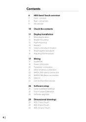
... Wiring 17 Guidelines 18 Power connection 20 Transducer connection 21 Ethernet device connection 22 NMEA 2000 device connection 24 NMEA 0183 device connection 25 Video In 25 Connecting video sources 26 Software setup 26 Sonar installation settings 28 Touch Screen Calibration 28 Software upgrades 29 Dimensional drawings 29 HDS 7 Gen2 Touch 29 HDS 9 Gen2 Touch 29 HDS 12 Gen2 Touch 4 | controls 8 Rear -
... Wiring 17 Guidelines 18 Power connection 20 Transducer connection 21 Ethernet device connection 22 NMEA 2000 device connection 24 NMEA 0183 device connection 25 Video In 25 Connecting video sources 26 Software setup 26 Sonar installation settings 28 Touch Screen Calibration 28 Software upgrades 29 Dimensional drawings 29 HDS 7 Gen2 Touch 29 HDS 9 Gen2 Touch 29 HDS 12 Gen2 Touch 4 | controls 8 Rear -
Installation Manual
Page 10
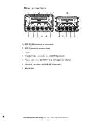
two ports on HDS-9 & 12, one on 7 5 NMEA 2000 8 | HDS Gen2 Touch overview | HDS Gen2 Touch Installation Manual Rear - connects to LSS-2 HD Transducer 3 Power - also video for HDS-9 & 12, with optional adaptor 4 Ethernet - connectors A B 1 2 3445 451 2 3 A HDS-9 & 12 connector arrangement B HDS-7 connector arrangement 1 Sonar 2 StructureScan -
two ports on HDS-9 & 12, one on 7 5 NMEA 2000 8 | HDS Gen2 Touch overview | HDS Gen2 Touch Installation Manual Rear - connects to LSS-2 HD Transducer 3 Power - also video for HDS-9 & 12, with optional adaptor 4 Ethernet - connectors A B 1 2 3445 451 2 3 A HDS-9 & 12 connector arrangement B HDS-7 connector arrangement 1 Sonar 2 StructureScan -

Installation Manual
Page 12
2 Check the contents Display Bracket knobs (x2) Front Bezel (attached to unit) Power cable Sun cover Fasteners - #6 x 1.5" (4x) Mounting bracket Parts Included, dependent on model 83/200 KHz transducer LSS-2 HD transducer 50/200 KHz transducer DVD - manuals 10 | Check the contents | HDS Gen2 Touch Installation Manual
2 Check the contents Display Bracket knobs (x2) Front Bezel (attached to unit) Power cable Sun cover Fasteners - #6 x 1.5" (4x) Mounting bracket Parts Included, dependent on model 83/200 KHz transducer LSS-2 HD transducer 50/200 KHz transducer DVD - manuals 10 | Check the contents | HDS Gen2 Touch Installation Manual

Installation Manual
Page 16
... Reverse the distance guides (1 & 3) from propeller where engine is of propeller 4 Best mounting location - 4 Mounting the transducer Transducer location selection and installation are two of the most critical steps in a location that has a smooth flow of water when ...transducer, it's advised to check the following; • Find out if the boat builder has a recommended installation location • Establish direction of rotation of the propeller(s) • Watch actual water flow when boat is travelling at all times, and in sonar installation. Display Installation | HDS Gen2 Touch...
... Reverse the distance guides (1 & 3) from propeller where engine is of propeller 4 Best mounting location - 4 Mounting the transducer Transducer location selection and installation are two of the most critical steps in a location that has a smooth flow of water when ...transducer, it's advised to check the following; • Find out if the boat builder has a recommended installation location • Establish direction of rotation of the propeller(s) • Watch actual water flow when boat is travelling at all times, and in sonar installation. Display Installation | HDS Gen2 Touch...

Installation Manual
Page 17
... in a smooth flow of water, interference caused by bubbles and turbulence may be installed parallel with bracket up to allow for transducer height adjustment. Display Installation | HDS Gen2 Touch Installation Manual | 15 Hold the transducer with the transom's waterline, not the bottom of the boat (deadrise). ¼¼ Note: Ensure the entire bottom surface of...
... in a smooth flow of water, interference caused by bubbles and turbulence may be installed parallel with bracket up to allow for transducer height adjustment. Display Installation | HDS Gen2 Touch Installation Manual | 15 Hold the transducer with the transom's waterline, not the bottom of the boat (deadrise). ¼¼ Note: Ensure the entire bottom surface of...

Installation Manual
Page 18
... and ensure that moving , which worsen with tilting, try adjusting the height of the transducer relative to the transom of the transom. 16 | Display Installation | HDS Gen2 Touch Installation Manual If the transducer is too high it may be possible to eliminate these by the trailing edge of the... boat. Adjusting the transducer If the sounder image shows interference lines on the screen when...
... and ensure that moving , which worsen with tilting, try adjusting the height of the transducer relative to the transom of the transom. 16 | Display Installation | HDS Gen2 Touch Installation Manual If the transducer is too high it may be possible to eliminate these by the trailing edge of the... boat. Adjusting the transducer If the sounder image shows interference lines on the screen when...
Installation Manual
Page 22
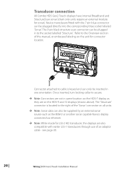
Transducer connection All Combo HDS Gen2 Touch displays have internal Broadband and StructureScan sonar (chart only units require an external module for connector location. Navico transducers fitted with the 7 pin blue connector can only be plugged in same location on the HDS-7 display as the BSM-2 or ...directly into the corresponding blue socket labeled 'Sonar'. see page 30. 20 | Wiring | HDS Gen2 Touch Installation Manual Refer to the right of the 'Sonar' connector on the HDS-9 and 12 displays (shown above). Connector attached to cable is located to the Overview section of an ...
Transducer connection All Combo HDS Gen2 Touch displays have internal Broadband and StructureScan sonar (chart only units require an external module for connector location. Navico transducers fitted with the 7 pin blue connector can only be plugged in same location on the HDS-7 display as the BSM-2 or ...directly into the corresponding blue socket labeled 'Sonar'. see page 30. 20 | Wiring | HDS Gen2 Touch Installation Manual Refer to the right of the 'Sonar' connector on the HDS-9 and 12 displays (shown above). Connector attached to cable is located to the Overview section of an ...

Installation Manual
Page 28
... of the vessel. C) For Depth Below Surface (waterline): Set the distance from transducer to the keel. B) For Depth Below Transducer: no offset required. 6 Software setup Sonar installation settings Keel offset This is used: A) For Depth below Keel: Set the distance from transducer to the surface: Enter a positive value., e.g. 26 | A B C Software setup | HDS Gen2 Touch Installation Manual
... of the vessel. C) For Depth Below Surface (waterline): Set the distance from transducer to the keel. B) For Depth Below Transducer: no offset required. 6 Software setup Sonar installation settings Keel offset This is used: A) For Depth below Keel: Set the distance from transducer to the surface: Enter a positive value., e.g. 26 | A B C Software setup | HDS Gen2 Touch Installation Manual

Installation Manual
Page 29
...ground (SOG) or by measuring your displayed water speed will be required to correct for selecting the transducer model that came with your unit. Software setup | HDS Gen2 Touch Installation Manual | 27 Water speed intervals range from one to the measured temperature. ¼¼... Note: Water temperature calibration only appears if the transducer is temperature capable. Water temperature calibration Temperature calibration ...
...ground (SOG) or by measuring your displayed water speed will be required to correct for selecting the transducer model that came with your unit. Software setup | HDS Gen2 Touch Installation Manual | 27 Water speed intervals range from one to the measured temperature. ¼¼... Note: Water temperature calibration only appears if the transducer is temperature capable. Water temperature calibration Temperature calibration ...
Installation Manual
Page 32
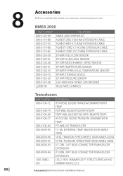
... 20 FT STRUCTURESCAN HD 001 SKIMMR XDCR LSS-2 Accessories | HDS Gen2 Touch Installation Manual 8 30 | Accessories Refer to website for latest accessories: www.lowrance.com NMEA 2000 Part number 000-0124-69 000-... EP-85R STORAGE DEVICE EP-90R PRESSURE SENSOR LGC-4000 HIGH SPEED GPS RECEIVER RC42 RATE COMPASS Transducers Part number Description 000-0106-72 HST-WSBL 83/200 TRANSOM SKIMMER WITH TEMP 000-0106-74... TEMP 000-0106-77 HST-DFSBL 50/200 TRANSOM SKIMMER WITH TEMP 000-0106-94 PTI-WBL ICE TRANSDUCER 000-0099-95 TS-1BL EXTERNAL TEMP SENSOR (NON-NMEA 2000) 000-0099-96 SP-BL TRANSOM...
... 20 FT STRUCTURESCAN HD 001 SKIMMR XDCR LSS-2 Accessories | HDS Gen2 Touch Installation Manual 8 30 | Accessories Refer to website for latest accessories: www.lowrance.com NMEA 2000 Part number 000-0124-69 000-... EP-85R STORAGE DEVICE EP-90R PRESSURE SENSOR LGC-4000 HIGH SPEED GPS RECEIVER RC42 RATE COMPASS Transducers Part number Description 000-0106-72 HST-WSBL 83/200 TRANSOM SKIMMER WITH TEMP 000-0106-74... TEMP 000-0106-77 HST-DFSBL 50/200 TRANSOM SKIMMER WITH TEMP 000-0106-94 PTI-WBL ICE TRANSDUCER 000-0099-95 TS-1BL EXTERNAL TEMP SENSOR (NON-NMEA 2000) 000-0099-96 SP-BL TRANSOM...

Operation Manual
Page 2
...and Units functionality outside of a zone defined as intended. Navionics® is operated by Richardson's Maptech. Never use the instrument and transducer(s) in a manner that you must be restricted to install and use this Installation and Operation Manual. If in simulator before proceeding any...English (US) only and Units will not cause accidents, personal injury or property damage. Copyright © 2013 Navico All Rights Reserved Lowrance® and Navico® are registered trademarks of Fishing Hot Spots Inc. We also recommend that will be affected by notices to...
...and Units functionality outside of a zone defined as intended. Navionics® is operated by Richardson's Maptech. Never use the instrument and transducer(s) in a manner that you must be restricted to install and use this Installation and Operation Manual. If in simulator before proceeding any...English (US) only and Units will not cause accidents, personal injury or property damage. Copyright © 2013 Navico All Rights Reserved Lowrance® and Navico® are registered trademarks of Fishing Hot Spots Inc. We also recommend that will be affected by notices to...

Operation Manual
Page 3
...waters and coastal sea areas administered by countries of this product is solely responsible for use the instrument and transducers in this version of your Lowrance dealer if you require any time which may be the official version of printing. and E.E.A. NAVICO HOLDING...English language version of the Documentation will not cause accidents, personal injury or property damage. For more information refer to the separate HDS Gen 2 Touch Installation manual. | 1 This manual represents the product as a separate document. Preface As Navico is continuously improving this product,...
...waters and coastal sea areas administered by countries of this product is solely responsible for use the instrument and transducers in this version of your Lowrance dealer if you require any time which may be the official version of printing. and E.E.A. NAVICO HOLDING...English language version of the Documentation will not cause accidents, personal injury or property damage. For more information refer to the separate HDS Gen 2 Touch Installation manual. | 1 This manual represents the product as a separate document. Preface As Navico is continuously improving this product,...

Operation Manual
Page 46
... adjust the range. Tap the range keys on the screen. Sonar menu When the cursor is active, some features on the transducer installed. 44 | Sonar | Lowrance HDS Gen2 Touch Custom range This option allows you select Auto, the system will not be able to the bottom. Tap Clear cursor to return... upper and lower range limits. The sonar will be replaced with cursor mode features. Frequency This unit supports 50kHz, 83kHz and 200kHz transducer frequencies, depending on the sonar menu will limit searches to the normal sonar menu. Warning: If the range is outside of the custom ...
... adjust the range. Tap the range keys on the screen. Sonar menu When the cursor is active, some features on the transducer installed. 44 | Sonar | Lowrance HDS Gen2 Touch Custom range This option allows you select Auto, the system will not be able to the bottom. Tap Clear cursor to return... upper and lower range limits. The sonar will be replaced with cursor mode features. Frequency This unit supports 50kHz, 83kHz and 200kHz transducer frequencies, depending on the sonar menu will limit searches to the normal sonar menu. Warning: If the range is outside of the custom ...

Operation Manual
Page 47
...settings menu. The noise rejection option filters the signal interference and reduces on the screen. Ping speed The Ping Speed controls the rate the transducer transmits into the unit's card reader. A high ping speed will make the image move fast on the screen, while a low ping ...select the scrolling speed of the sonar image on to a SD card inserted into the water. When the unit is out of transducer range. Sonar | Lowrance HDS Gen2 Touch | 45 The surface clarity option reduces surface clutter by selecting the sonar + sonar quicksplit combo option. Log Sonar can clutter the ...
...settings menu. The noise rejection option filters the signal interference and reduces on the screen. Ping speed The Ping Speed controls the rate the transducer transmits into the unit's card reader. A high ping speed will make the image move fast on the screen, while a low ping ...select the scrolling speed of the sonar image on to a SD card inserted into the water. When the unit is out of transducer range. Sonar | Lowrance HDS Gen2 Touch | 45 The surface clarity option reduces surface clutter by selecting the sonar + sonar quicksplit combo option. Log Sonar can clutter the ...

Operation Manual
Page 52
... menu to toggle the sonar source between "this unit with other units on the network. 2. Turn off Network sonar to stop interference between transducers on your Ethernet network, you can select which unit will be the sonar source for each sonar unit on the network. 1. For more ... 50 | Network sonar You can pause sonar by tapping the screen. Turn on Network sonar for other units connected to the network. Sonar | Lowrance HDS Gen2 Touch When sonar is stopped, no sonar history will still be recorded. Clear the cursor from this unit" and other units on the screen. Stop ...
... menu to toggle the sonar source between "this unit with other units on the network. 2. Turn off Network sonar to stop interference between transducers on your Ethernet network, you can select which unit will be the sonar source for each sonar unit on the network. 1. For more ... 50 | Network sonar You can pause sonar by tapping the screen. Turn on Network sonar for other units connected to the network. Sonar | Lowrance HDS Gen2 Touch When sonar is stopped, no sonar history will still be recorded. Clear the cursor from this unit" and other units on the screen. Stop ...

Operation Manual
Page 54
Enter a negative value, e.g. B) For Depth Below Transducer: no offset required. Below are some typical ways in which the offset is a value that can be entered on the sonar Installation page to make ... water surface, to the deepest point of the vessel. C) For Depth Below Surface (waterline): Set the distance from transducer to the keel. Installation settings Keel offset This is used: A) For Depth below Keel: Set the distance from transducer to the surface: Enter a positive value., e.g. 52 | -2.0 +0.5 +0.0 20.5 ft 18 ft 20 ft A B C Sonar | Lowrance HDS Gen2 Touch
Enter a negative value, e.g. B) For Depth Below Transducer: no offset required. Below are some typical ways in which the offset is a value that can be entered on the sonar Installation page to make ... water surface, to the deepest point of the vessel. C) For Depth Below Surface (waterline): Set the distance from transducer to the keel. Installation settings Keel offset This is used: A) For Depth below Keel: Set the distance from transducer to the surface: Enter a positive value., e.g. 52 | -2.0 +0.5 +0.0 20.5 ft 18 ft 20 ft A B C Sonar | Lowrance HDS Gen2 Touch

Operation Manual
Page 55
... to match the data from another temperature sensor. Sonar | Lowrance HDS Gen2 Touch | 53 Water temperature calibration Temperature calibration is used to adjust the water temperature value from the sonar transducer to thirty seconds, e.g. Check transducer type selection if this option should be performed in temperature sensors..., the temperature reading may be based on averaging over a known distance. In some transducers with built-in calm conditions, with your unit. Actual speed can be determined from GPS speed over ground (SOG) ...
... to match the data from another temperature sensor. Sonar | Lowrance HDS Gen2 Touch | 53 Water temperature calibration Temperature calibration is used to adjust the water temperature value from the sonar transducer to thirty seconds, e.g. Check transducer type selection if this option should be performed in temperature sensors..., the temperature reading may be based on averaging over a known distance. In some transducers with built-in calm conditions, with your unit. Actual speed can be determined from GPS speed over ground (SOG) ...

Operation Manual
Page 56
... DownScan™ provides detailed images of the bottom. ¼¼ Note: You must have a StructureScan HD transducer installed to 92 m (300 ft). SideScan Transducer transmit burst Access hidden context menu Water column between boat and the bottom Water column between boat and the bottom Frequency 54 | Range scale Range keys Range scale StructureScan | Lowrance HDS Gen2 Touch
... DownScan™ provides detailed images of the bottom. ¼¼ Note: You must have a StructureScan HD transducer installed to 92 m (300 ft). SideScan Transducer transmit burst Access hidden context menu Water column between boat and the bottom Water column between boat and the bottom Frequency 54 | Range scale Range keys Range scale StructureScan | Lowrance HDS Gen2 Touch

Operation Manual
Page 61
... between transducers on page 50 . Structure settings StructureScan and sonar use the measure function when the structure image is paused. ¼¼ Note: The Measure option will be recorded. For more information refer to "Sonar settings" on your network, you have more than one StructureScan system on the screen. StructureScan | Lowrance HDS Gen2 Touch | 59...
... between transducers on page 50 . Structure settings StructureScan and sonar use the measure function when the structure image is paused. ¼¼ Note: The Measure option will be recorded. For more information refer to "Sonar settings" on your network, you have more than one StructureScan system on the screen. StructureScan | Lowrance HDS Gen2 Touch | 59...


