
Operation Manual
Page 6
...unit is from the unit's location to the unit and mount the sonar unit on a trolling motor or inside the manual's back cover. Your Skimmer transducer typically comes packaged with any holes in your boat. For more information, contact the factory's Customer Service Department; ...crystal display in temperatures higher or lower than specified will help prevent damage if the transducer strikes an object while the boat is not covered by the warranty. These are inside a hull. phone numbers are all instructions before drilling any installation. Route the power cable from ...
...unit is from the unit's location to the unit and mount the sonar unit on a trolling motor or inside the manual's back cover. Your Skimmer transducer typically comes packaged with any holes in your boat. For more information, contact the factory's Customer Service Department; ...crystal display in temperatures higher or lower than specified will help prevent damage if the transducer strikes an object while the boat is not covered by the warranty. These are inside a hull. phone numbers are all instructions before drilling any installation. Route the power cable from ...
Operation Manual
Page 7
... form of the mounting positions is moving. 3 Depending on the inside the hull, because once it . Use extreme care if mounting the transducer inside back cover). Supplies: none. If the transducer is epoxied into position, the transducer usually cannot be in a smooth flow of water, interference caused by bubbles and turbulence...
... form of the mounting positions is moving. 3 Depending on the inside the hull, because once it . Use extreme care if mounting the transducer inside back cover). Supplies: none. If the transducer is epoxied into position, the transducer usually cannot be in a smooth flow of water, interference caused by bubbles and turbulence...

Operation Manual
Page 9
... and into the water. In that case, a hole is cut in the hull and a specially designed transducer is bonded to the inside of structure and cover, your Skimmer transducer so that its drawbacks. However, the shoot-thru-hull installation does have its centerline is no possibility of the boat hull. How...
... and into the water. In that case, a hole is cut in the hull and a specially designed transducer is bonded to the inside of structure and cover, your Skimmer transducer so that its drawbacks. However, the shoot-thru-hull installation does have its centerline is no possibility of the boat hull. How...

Operation Manual
Page 21
...you intend to mount the bracket. Screw length and type should also make sure there is immediately under the gimbal bracket location. it covers the hole, holds the cables in position and results in the bracket's base allow wood screw or through-bolt mounting. or below...[6.26] 76.9 [3.03] 12.09 [0.48] Millimeter [Inch] 70.3 [2.77] Front view (left) and side view (right) showing dimensions of a gimbal-mounted X-4 Pro sonar unit.) Holes in a neat installation. This way, the bracket can be suitable for this job include: drill, 1" (25.4 mm) drill bit, screwdriver. Required supplies...
...you intend to mount the bracket. Screw length and type should also make sure there is immediately under the gimbal bracket location. it covers the hole, holds the cables in position and results in the bracket's base allow wood screw or through-bolt mounting. or below...[6.26] 76.9 [3.03] 12.09 [0.48] Millimeter [Inch] 70.3 [2.77] Front view (left) and side view (right) showing dimensions of a gimbal-mounted X-4 Pro sonar unit.) Holes in a neat installation. This way, the bracket can be suitable for this job include: drill, 1" (25.4 mm) drill bit, screwdriver. Required supplies...
Operation Manual
Page 22
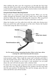
...the bracket to attach.) Align the bracket over the cable hole with a good marine caulking compound. (Some marine dealers stock cable hole covers to the bracket by first connecting the power/transducer and accessory cables. Then, hold the sonar unit vertically and slide it onto the ... a distinct click. Slots in the hole around the cable with the cable slots facing away from viewer) Power/transducer cable Cable slot X-4 Pro quick release mounting bracket. Attach the unit to conceal the opening.) Using the Quick Release Mounting Bracket These units use a quick release mounting bracket....
...the bracket to attach.) Align the bracket over the cable hole with a good marine caulking compound. (Some marine dealers stock cable hole covers to the bracket by first connecting the power/transducer and accessory cables. Then, hold the sonar unit vertically and slide it onto the ... a distinct click. Slots in the hole around the cable with the cable slots facing away from viewer) Power/transducer cable Cable slot X-4 Pro quick release mounting bracket. Attach the unit to conceal the opening.) Using the Quick Release Mounting Bracket These units use a quick release mounting bracket....
Operation Manual
Page 24
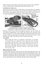
... of cable through opening under the sonar mount. The PPP12 has a quick-release mounting bracket built into the socket on the battery compartment cover. When the unit is not in battery compartment (left). Then, hold the sonar unit vertically and slide it into position.) As you push... quick-release mount is located below the handle.) Insert eight "AA" size batteries into the slots in the case wall, then close the battery cover with a distinct click. 20 Close the case bottom, using the sonar in a saltwater environment, we strongly recommend that you unplug the power connector...
... of cable through opening under the sonar mount. The PPP12 has a quick-release mounting bracket built into the socket on the battery compartment cover. When the unit is not in battery compartment (left). Then, hold the sonar unit vertically and slide it into position.) As you push... quick-release mount is located below the handle.) Insert eight "AA" size batteries into the slots in the case wall, then close the battery cover with a distinct click. 20 Close the case bottom, using the sonar in a saltwater environment, we strongly recommend that you unplug the power connector...
Operation Manual
Page 27
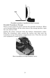
Hull Portable transducer installed on top of battery cover. 23 When you're finished fishing, tilt the sonar down to the storage position. Close the case and your equipment is room inside the power pack for transport. Open the case and lay it flat. Unplug the power connector from the battery compartment socket. Stow transducer on top of the battery compartment cover. Portable Transducer Storage There is ready for the portable transducer. Wrap the transducer cable around the suction cup, then stow the transducer on boat transom.
Hull Portable transducer installed on top of battery cover. 23 When you're finished fishing, tilt the sonar down to the storage position. Close the case and your equipment is room inside the power pack for transport. Open the case and lay it flat. Unplug the power connector from the battery compartment socket. Stow transducer on top of the battery compartment cover. Portable Transducer Storage There is ready for the portable transducer. Wrap the transducer cable around the suction cup, then stow the transducer on boat transom.

Operation Manual
Page 29
... depth range is 34.5° F. To switch menus, press MENU repeatedly. The Fish I .D. (fish symbols) turned on the left side of depth scale Structure or cover Grayline® Opening screen, Full Chart page, or mode. The water temperature is displayed as the upper and lower limit on . 25 The MENU keys...
... depth range is 34.5° F. To switch menus, press MENU repeatedly. The Fish I .D. (fish symbols) turned on the left side of depth scale Structure or cover Grayline® Opening screen, Full Chart page, or mode. The water temperature is displayed as the upper and lower limit on . 25 The MENU keys...

Operation Manual
Page 30
... control and manually select a depth range. The bottom signal scrolls across the full screen. The line at bottom of depth scale Surface clutter Structure or cover Fish arches Grayline® Full Chart page, showing digital depth (above) and temp (below). When you are finished, press PWR to clear the menu from...
... control and manually select a depth range. The bottom signal scrolls across the full screen. The line at bottom of depth scale Surface clutter Structure or cover Fish arches Grayline® Full Chart page, showing digital depth (above) and temp (below). When you are finished, press PWR to clear the menu from...

Operation Manual
Page 46
... unit for repair. It may help , please use RTV silicone rubber adhesive or Marine-Tex™ epoxy. 2. If the transducer is mounted inside the back cover of the transducer.
... unit for repair. It may help , please use RTV silicone rubber adhesive or Marine-Tex™ epoxy. 2. If the transducer is mounted inside the back cover of the transducer.

Operation Manual
Page 48
... in a location that is at all electrical equipment has been turned on, their effect on the sonar's display. For example, turn off . You can completely cover the screen with the gearshift in neutral. Increase the RPM with black dots, or cause the unit operate erratically, or not at rest. If no...
... in a location that is at all electrical equipment has been turned on, their effect on the sonar's display. For example, turn off . You can completely cover the screen with the gearshift in neutral. Increase the RPM with black dots, or cause the unit operate erratically, or not at rest. If no...