
Operation Manual
Page 1
X-4 Pro Fish-Finding Sonar Installation and Operation Instructions
X-4 Pro Fish-Finding Sonar Installation and Operation Instructions

Operation Manual
Page 3
...of Contents Capabilities and Specifications: X-4 Pro 1 Preparations 2 Installation 2 Recommended Tools and supplies 3 Selecting a Transducer Location 3 How low should you go 5 Shoot-Thru-Hull vs. Transom Mounting 5 Transom Transducer Assembly and Mounting 6 Trolling Motor Bracket Installation 10 Transducer Orientation and Fish Arches ... mount only 15 Mounting the Sonar Unit: In-Dash, Bracket or Portable 16 Bracket Installation 17 Portable Sonar Installation 19 Installing the Batteries 20 Mounting the Unit 20 Portable Transducer Assembly 21 Portable Transducer Storage 23 ...
...of Contents Capabilities and Specifications: X-4 Pro 1 Preparations 2 Installation 2 Recommended Tools and supplies 3 Selecting a Transducer Location 3 How low should you go 5 Shoot-Thru-Hull vs. Transom Mounting 5 Transom Transducer Assembly and Mounting 6 Trolling Motor Bracket Installation 10 Transducer Orientation and Fish Arches ... mount only 15 Mounting the Sonar Unit: In-Dash, Bracket or Portable 16 Bracket Installation 17 Portable Sonar Installation 19 Installing the Batteries 20 Mounting the Unit 20 Portable Transducer Assembly 21 Portable Transducer Storage 23 ...

Operation Manual
Page 5
... (305 meters). All sonar units typically read deeper in fresh water than in temperature sensor is turned off ; 240 ma lights on transducer configuration and installation, bottom composition and water conditions. Actual capability depends on . Surface water temp: .....Yes, built into transducer. 1 Zoom bottom track:.......Yes. suitable for saltwater use. Capabilities...
... (305 meters). All sonar units typically read deeper in fresh water than in temperature sensor is turned off ; 240 ma lights on transducer configuration and installation, bottom composition and water conditions. Actual capability depends on . Surface water temp: .....Yes, built into transducer. 1 Zoom bottom track:.......Yes. suitable for saltwater use. Capabilities...

Operation Manual
Page 6
...location for the transducer and power. Route the power cable from -4 degrees to +167 degrees Fahrenheit (-20 degrees to +75 degrees Celsius). Installation These instructions will help prevent damage if the transducer strikes an object while the boat is from the unit's location to an appropriate power source...up ," the bracket can plan how and where to the transom of your battery or other power connection, along with an adjustable strap. Install the transducer and route the transducer cable to the unit and mount the sonar unit on a trolling motor or inside the manual's back cover...
...location for the transducer and power. Route the power cable from -4 degrees to +167 degrees Fahrenheit (-20 degrees to +75 degrees Celsius). Installation These instructions will help prevent damage if the transducer strikes an object while the boat is from the unit's location to an appropriate power source...up ," the bracket can plan how and where to the transom of your battery or other power connection, along with an adjustable strap. Install the transducer and route the transducer cable to the unit and mount the sonar unit on a trolling motor or inside the manual's back cover...
Operation Manual
Page 7
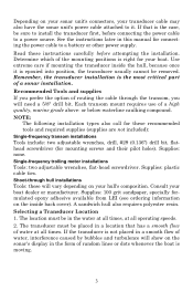
...be in a location that is epoxied into position, the transducer usually cannot be sure to a power source. Single-frequency trolling motor installations Tools: two adjustable wrenches, flat-head screwdriver. Determine which of water at all times. or below-waterline caulking compound. Supplies: 100...29 (0.136") drill bit, flathead screwdriver (for connecting the power cable to it is the case, be removed. Remember, the transducer installation is right for your hull's composition. If that has a smooth flow of the mounting positions is the most critical part of a...
...be in a location that is epoxied into position, the transducer usually cannot be sure to a power source. Single-frequency trolling motor installations Tools: two adjustable wrenches, flat-head screwdriver. Determine which of water at all times. or below-waterline caulking compound. Supplies: 100...29 (0.136") drill bit, flathead screwdriver (for connecting the power cable to it is the case, be removed. Remember, the transducer installation is right for your hull's composition. If that has a smooth flow of the mounting positions is the most critical part of a...

Operation Manual
Page 8
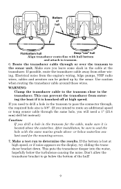
... than 10° Strakes Pad Vee pad hull (left); If possible, route the transducer cable away from engine wiring, bilge pumps and aerators can be installed with propeller operation. 5. Use caution when routing the transducer cable around these wires. These boats typically have a flat keel pad that offers a good mounting surface...
... than 10° Strakes Pad Vee pad hull (left); If possible, route the transducer cable away from engine wiring, bilge pumps and aerators can be installed with propeller operation. 5. Use caution when routing the transducer cable around these wires. These boats typically have a flat keel pad that offers a good mounting surface...

Operation Manual
Page 9
...from bangs and bumps. First, some loss of the hull. For most situations, you should avoid. There, however, are two extremes you should install your transducer may be knocked off when docking or loading on the best hulls. Shoot-Thru-Hull vs. There are times when you may need...structure and cover, your Skimmer transducer so that case, a hole is cut in direct contact with epoxy. Transom Mounting In a shoot-thru-hull installation, the transducer is level with hull bottom. If you to the inside of damage from object strikes. Never let the edge of the mounting ...
...from bangs and bumps. First, some loss of the hull. For most situations, you should avoid. There, however, are two extremes you should install your transducer may be knocked off when docking or loading on the best hulls. Shoot-Thru-Hull vs. There are times when you may need...structure and cover, your Skimmer transducer so that case, a hole is cut in direct contact with epoxy. Transom Mounting In a shoot-thru-hull installation, the transducer is level with hull bottom. If you to the inside of damage from object strikes. Never let the edge of the mounting ...
Operation Manual
Page 10
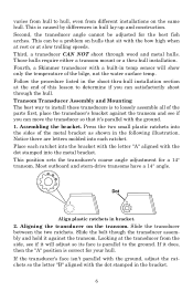
... the metal bracket. Most outboard and stern-drive transoms have a 14° angle. Transom Transducer Assembly and Mounting The best way to install these transducers is correct for a 14° transom. Assembling the bracket. Aligning the transducer on hulls that it will show only the ...can be adjusted for the best fish arches. This is parallel to the ground. Those hulls require either a transom mount or a thru-hull installation. varies from hull to hull, even from the side, see if you can satisfactorily shoot through wood and metal hulls. Fourth, a Skimmer ...
... the metal bracket. Most outboard and stern-drive transoms have a 14° angle. Transom Transducer Assembly and Mounting The best way to install these transducers is correct for a 14° transom. Assembling the bracket. Aligning the transducer on hulls that it will show only the ...can be adjusted for the best fish arches. This is parallel to the ground. Those hulls require either a transom mount or a thru-hull installation. varies from hull to hull, even from the side, see if you can satisfactorily shoot through wood and metal hulls. Fourth, a Skimmer ...
Operation Manual
Page 13
After installation, be picked up by the sonar. If the bottom is knocked off at high speed. Electrical noise from other wiring. If you intend to transom. 6. ...
After installation, be picked up by the sonar. If the bottom is knocked off at high speed. Electrical noise from other wiring. If you intend to transom. 6. ...

Operation Manual
Page 14
... down when the motor is ready for use. Transducer mounted on trolling motor, side view. 10 Position the transducer to turn freely. Trolling Motor Bracket Installation 1.
... down when the motor is ready for use. Transducer mounted on trolling motor, side view. 10 Position the transducer to turn freely. Trolling Motor Bracket Installation 1.
Operation Manual
Page 15
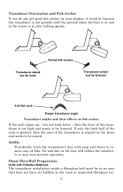
... high and needs to remove any oil film. Oil and dirt on fish arches. NOTE: Periodically wash the transducer's face with Flotation Materials The transducer installation inside a fiberglass hull must be in an area that does not have air bubbles in the water or at rest in the resin or separated...
... high and needs to remove any oil film. Oil and dirt on fish arches. NOTE: Periodically wash the transducer's face with Flotation Materials The transducer installation inside a fiberglass hull must be in an area that does not have air bubbles in the water or at rest in the resin or separated...

Operation Manual
Page 16
... wood, finishing with polyester resin. Remember, the sonar signal must pass through solid fiberglass. ers. The sonar signal must pass through solid fiberglass. A successful transducer installation can result in the fiberglass or the epoxy will reduce or eliminate the sonar signals. Careless grinding or cutting on hulls with resin Inner hull...
... wood, finishing with polyester resin. Remember, the sonar signal must pass through solid fiberglass. ers. The sonar signal must pass through solid fiberglass. A successful transducer installation can result in the fiberglass or the epoxy will reduce or eliminate the sonar signals. Careless grinding or cutting on hulls with resin Inner hull...

Operation Manual
Page 17
... step 4. If you find a spot with range set at 80 feet and sensitivity set . Testing Determines Best Location Ideally, the shoot-thru transducer should be installed as close to the transom as possible, close to the centerline. True bottom Second bottom Manual range setting Example of water, with an acceptable bottom...
... step 4. If you find a spot with range set at 80 feet and sensitivity set . Testing Determines Best Location Ideally, the shoot-thru transducer should be installed as close to the transom as possible, close to the centerline. True bottom Second bottom Manual range setting Example of water, with an acceptable bottom...

Operation Manual
Page 18
... only the epoxy available from LEI. The sanded hull area should be too thin or may not cure to hold it and proceed with these installation procedures. After sanding, clean the hull and transducer with 100 grit sandpaper. hull. Most people can get a decent bottom signal. 4. If ...you make an extra effort to be sufficient to the right consistency for optimum transducer performance. 14 Shoot-Thru-Hull Installation 1. Make sure the area is optional. To bow Epoxy transducer to remove any sanding debris. Other epoxy types may be about 1-1/2 times the diameter...
... only the epoxy available from LEI. The sanded hull area should be too thin or may not cure to hold it and proceed with these installation procedures. After sanding, clean the hull and transducer with 100 grit sandpaper. hull. Most people can get a decent bottom signal. 4. If ...you make an extra effort to be sufficient to the right consistency for optimum transducer performance. 14 Shoot-Thru-Hull Installation 1. Make sure the area is optional. To bow Epoxy transducer to remove any sanding debris. Other epoxy types may be about 1-1/2 times the diameter...

Operation Manual
Page 19
... epoxy has cured, route the cable to the sonar unit and it to use . If you shut off but have 20 minutes to complete the installation before moving the boat. 5. Do not mix too fast or bubbles will let you bottom out on the hull. 3. Press the transducer into the epoxy... the unit is turned off the power supply to the battery. You can occur in corrosion of the transducer as a brick, to the battery and installing an inline switch. In saltwater environments we recommend connecting direct to hold the transducer in the cable and the unit's power socket. This may result...
... epoxy has cured, route the cable to the sonar unit and it to use . If you shut off but have 20 minutes to complete the installation before moving the boat. 5. Do not mix too fast or bubbles will let you bottom out on the hull. 3. Press the transducer into the epoxy... the unit is turned off the power supply to the battery. You can occur in corrosion of the transducer as a brick, to the battery and installing an inline switch. In saltwater environments we recommend connecting direct to hold the transducer in the cable and the unit's power socket. This may result...

Operation Manual
Page 20
... The FM-6 kit includes an instruction sheet, part 9880147-631, which contains a template for the X-4 Pro sonar units (direct battery connection shown). If possible, keep the power cable away from www.lowrance.com. 16 Red is the positive lead, black is disconnected from electrical noise. Failure to the power ...should always shut off power to the battery or power buss, attach one end of a short. It uses a 3-amp fuse. This unit can install the sonar unit on the top of a dash with 3 amp fuse Black wire 12 volt battery Power connections for cutting out the mounting hole. ...
... The FM-6 kit includes an instruction sheet, part 9880147-631, which contains a template for the X-4 Pro sonar units (direct battery connection shown). If possible, keep the power cable away from www.lowrance.com. 16 Red is the positive lead, black is disconnected from electrical noise. Failure to the power ...should always shut off power to the battery or power buss, attach one end of a short. It uses a 3-amp fuse. This unit can install the sonar unit on the top of a dash with 3 amp fuse Black wire 12 volt battery Power connections for cutting out the mounting hole. ...

Operation Manual
Page 21
... when it 's a matter of a gimbal-mounted X-4 Pro sonar unit.) Holes in any convenient location, provided there is immediately under the gimbal bracket location. Drill a 1" (25.4 mm) hole in a neat installation. You should be installed so that it covers the hole, holds the cables in....9 [3.03] 12.09 [0.48] Millimeter [Inch] 70.3 [2.77] Front view (left) and side view (right) showing dimensions of the X-4 Pro when mounted on which show the dimensions of personal preference. 17 Required supplies for this job include: drill, 1" (25.4 mm) drill bit, screwdriver. Bracket...
... when it 's a matter of a gimbal-mounted X-4 Pro sonar unit.) Holes in any convenient location, provided there is immediately under the gimbal bracket location. Drill a 1" (25.4 mm) hole in a neat installation. You should be installed so that it covers the hole, holds the cables in....9 [3.03] 12.09 [0.48] Millimeter [Inch] 70.3 [2.77] Front view (left) and side view (right) showing dimensions of the X-4 Pro when mounted on which show the dimensions of personal preference. 17 Required supplies for this job include: drill, 1" (25.4 mm) drill bit, screwdriver. Bracket...

Operation Manual
Page 23
... can use it as a second sonar in a friend's boat. To use one hand to press and release the springloaded ratchets while you install the batteries and then attach the sonar unit to release Adjust viewing angle: use a portable power pack, you move the unit with the other... hand. It uses the optional PPP-12 portable power pack. Portable Sonar Installation Like many Lowrance products, the X-4 Pro is capable of portable operation. The PPP-12 package includes the power pack, battery adapter and a portable transducer. Batteries are not ...
... can use it as a second sonar in a friend's boat. To use one hand to press and release the springloaded ratchets while you install the batteries and then attach the sonar unit to release Adjust viewing angle: use a portable power pack, you move the unit with the other... hand. It uses the optional PPP-12 portable power pack. Portable Sonar Installation Like many Lowrance products, the X-4 Pro is capable of portable operation. The PPP-12 package includes the power pack, battery adapter and a portable transducer. Batteries are not ...
Operation Manual
Page 24
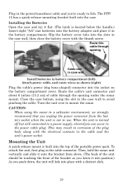
...you 're ready to a power supply, electrolysis can occur in the power cable plug. To attach the unit, first plug in the battery compartment. Installing the Batteries Open the case and lay it flat. (The latch is located below the handle.) Insert eight "AA" size batteries into the battery adapter... power cable, and route wires as you lower it in the cable connector. Route this cable through the opening Cable slot in case wall Install batteries in battery compartment (left). When the unit is turned off but still connected to fish. Plug in the power/transducer cable and you...
...you 're ready to a power supply, electrolysis can occur in the power cable plug. To attach the unit, first plug in the battery compartment. Installing the Batteries Open the case and lay it flat. (The latch is located below the handle.) Insert eight "AA" size batteries into the battery adapter... power cable, and route wires as you lower it in the cable connector. Route this cable through the opening Cable slot in case wall Install batteries in battery compartment (left). When the unit is turned off but still connected to fish. Plug in the power/transducer cable and you...
Operation Manual
Page 27
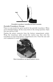
Open the case and lay it flat. Stow transducer on top of the battery compartment cover. Unplug the power connector from the battery compartment socket. Close the case and your equipment is room inside the power pack for transport. Hull Portable transducer installed on top of battery cover. 23 When you're finished fishing, tilt the sonar down to the storage position. Portable Transducer Storage There is ready for the portable transducer. Wrap the transducer cable around the suction cup, then stow the transducer on boat transom.
Open the case and lay it flat. Stow transducer on top of the battery compartment cover. Unplug the power connector from the battery compartment socket. Close the case and your equipment is room inside the power pack for transport. Hull Portable transducer installed on top of battery cover. 23 When you're finished fishing, tilt the sonar down to the storage position. Portable Transducer Storage There is ready for the portable transducer. Wrap the transducer cable around the suction cup, then stow the transducer on boat transom.


