User Manual
Page 13
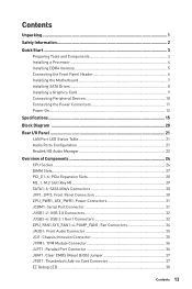
... Ports Configuration 21 Realtek HD Audio Manager 22 Overview of Components 24 CPU Socket ...26 DIMM Slots...27 PCI_E1~6: PCIe Expansion Slots 28 M2_1: M.2 Slot (Key M 29 SATA1~6: SATA 6Gb/s Connectors 30 JFP1, JFP2: Front Panel Connectors 30 CPU_PWR1, ATX_PWR1: Power Connectors 31 JCOM1: Serial Port Connector 31 JUSB1~2: USB 2.0 ...34 JAUD1: Front Audio Connector 35 JCI1: Chassis Intrusion Connector 35 JTPM1: TPM Module Connector 36 JLPT1: Parallel Port Connector 36 JBAT1: Clear CMOS (Reset BIOS) Jumper 37 JTBT1: Thunderbolt Add-on Card Connector 37 EZ Debug LED...38 Contents 13
... Ports Configuration 21 Realtek HD Audio Manager 22 Overview of Components 24 CPU Socket ...26 DIMM Slots...27 PCI_E1~6: PCIe Expansion Slots 28 M2_1: M.2 Slot (Key M 29 SATA1~6: SATA 6Gb/s Connectors 30 JFP1, JFP2: Front Panel Connectors 30 CPU_PWR1, ATX_PWR1: Power Connectors 31 JCOM1: Serial Port Connector 31 JUSB1~2: USB 2.0 ...34 JAUD1: Front Audio Connector 35 JCI1: Chassis Intrusion Connector 35 JTPM1: TPM Module Connector 36 JLPT1: Parallel Port Connector 36 JBAT1: Clear CMOS (Reset BIOS) Jumper 37 JTBT1: Thunderbolt Add-on Card Connector 37 EZ Debug LED...38 Contents 13

User Manual
Page 25
...Power Connectors CPU Socket LGA1151 CPU Socket DIMMA1/ A2/ B1/ B2 DIMM Slots JAUD1 JBAT1 JCI1 Front Audio Connector Clear CMOS (Reset BIOS) Jumper Chassis Intrusion Connector JCOM1 Serial Port Connector JFP1, JFP2 Front Panel Connectors JLPT1 JTBT1 JTPM1 Parallel Port Connector Thunderbolt Add-on Card ...Connector TPM Module Connector JUSB1~2 USB 2.0 Connectors JUSB3~4 USB 3.1 Gen1 Connectors M2_1 M.2 Slot (Key M) PCI_E1~6 PCIe Expansion Slots SATA1~6 SATA 6Gb/s Connectors Page 34 31 26 27 35 37 35 31 30 36 37 36 32 32...
...Power Connectors CPU Socket LGA1151 CPU Socket DIMMA1/ A2/ B1/ B2 DIMM Slots JAUD1 JBAT1 JCI1 Front Audio Connector Clear CMOS (Reset BIOS) Jumper Chassis Intrusion Connector JCOM1 Serial Port Connector JFP1, JFP2 Front Panel Connectors JLPT1 JTBT1 JTPM1 Parallel Port Connector Thunderbolt Add-on Card ...Connector TPM Module Connector JUSB1~2 USB 2.0 Connectors JUSB3~4 USB 3.1 Gen1 Connectors M2_1 M.2 Slot (Key M) PCI_E1~6 PCIe Expansion Slots SATA1~6 SATA 6Gb/s Connectors Page 34 31 26 27 35 37 35 31 30 36 37 36 32 32...

User Manual
Page 35
... on the chassis. 2. Press F10 to save and exit and then press the Enter key to the chassis intrusion switch/ sensor on . Go to Enabled. 5. Set Chassis Intrusion to BIOS > SETTINGS > Security > Chassis Intrusion Configuration. 4. Resetting the chassis intrusion warning 1. ...Go to Reset. 3. Overview of Components 35 Set Chassis Intrusion to BIOS > SETTINGS > Security > Chassis Intrusion Configuration. 2. Normal (default) Trigger the chassis intrusion event Using chassis intrusion detector 1....
... on the chassis. 2. Press F10 to save and exit and then press the Enter key to the chassis intrusion switch/ sensor on . Go to Enabled. 5. Set Chassis Intrusion to BIOS > SETTINGS > Security > Chassis Intrusion Configuration. 4. Resetting the chassis intrusion warning 1. ...Go to Reset. 3. Overview of Components 35 Set Chassis Intrusion to BIOS > SETTINGS > Security > Chassis Intrusion Configuration. 2. Normal (default) Trigger the chassis intrusion event Using chassis intrusion detector 1....

User Manual
Page 39
Therefore, the description may vary from the latest BIOS and should always keep the default settings to the HELP information panel for reference only and may be for reference only. Click on GO2BIOS Function key F1: General Help F2: Add/ Remove a favorite item F3: Enter ... possible system damage or failure booting unless you purchased. y Press Delete key, when the Press DEL key to enter Setup Menu, F11 to enter BIOS setup. Important y BIOS items are for BIOS item description. y Use MSI FAST BOOT application. You should be slightly different from the product you ...
Therefore, the description may vary from the latest BIOS and should always keep the default settings to the HELP information panel for reference only and may be for reference only. Click on GO2BIOS Function key F1: General Help F2: Add/ Remove a favorite item F3: Enter ... possible system damage or failure booting unless you purchased. y Press Delete key, when the Press DEL key to enter Setup Menu, F11 to enter BIOS setup. Important y BIOS items are for BIOS item description. y Use MSI FAST BOOT application. You should be slightly different from the product you ...

User Manual
Page 40
...Click on Scan button. 4. And then save the BIOS file into the computer. 3. Insert the USB flash drive that matches your motherboard model from MSI website. Updating the BIOS with M-FLASH Before updating: Please download the latest BIOS file that contains the update file into the USB ... problems. There are several ways to reset BIOS: y Go to BIOS and press F6 to perform the BIOS update process. 5. Press Del key to start updating BIOS. 6. Updating BIOS: 1. And then click Next and Start to enter the BIOS Setup during POST. 2. Updating BIOS: 1. Please refer to reboot the system ...
...Click on Scan button. 4. And then save the BIOS file into the computer. 3. Insert the USB flash drive that matches your motherboard model from MSI website. Updating the BIOS with M-FLASH Before updating: Please download the latest BIOS file that contains the update file into the USB ... problems. There are several ways to reset BIOS: y Go to BIOS and press F6 to perform the BIOS update process. 5. Press Del key to start updating BIOS. 6. Updating BIOS: 1. And then click Next and Start to enter the BIOS Setup during POST. 2. Updating BIOS: 1. Please refer to reboot the system ...

User Manual
Page 41
... Profile). click on this tab or the F12 key to take a screenshot and save it to USB flash drive (FAT/ FAT32 format only). shows the CPU/ DDR speed, CPU/ MB temperature, MB/ CPU type, memory size, CPU/ DDR voltage, BIOS version and build date. you to search by pressing... the Setup Mode switch or F7 function key. XMP switch Setup Mode switch Screenshot Search Language System information OC GENIE 4 switch Information display Boot device...
... Profile). click on this tab or the F12 key to take a screenshot and save it to USB flash drive (FAT/ FAT32 format only). shows the CPU/ DDR speed, CPU/ MB temperature, MB/ CPU type, memory size, CPU/ DDR voltage, BIOS version and build date. you to search by pressing... the Setup Mode switch or F7 function key. XMP switch Setup Mode switch Screenshot Search Language System information OC GENIE 4 switch Information display Boot device...
User Manual
Page 42
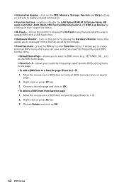
...menu - press the F3 key to select a BIOS menu (e.g. SETTINGS, OC...,etc) as the BIOS home page. ƒ Favorite1~5 - Right-click or press F2 key. 3. enable or disable the LAN Option ROM, M.2/ Optane Genie, HD audio controller, AHCI, RAID, CPU Fan Fail Warning Control and BIOS Log Review by percentage....Move the mouse over a BIOS item not only on BIOS menu but also on their respective button. Right-click or press F2 key. 3. It allows you can save and access favorite/ frequently-used / favorite BIOS setting items in one page. ƒ To add a BIOS item to display related information...
...menu - press the F3 key to select a BIOS menu (e.g. SETTINGS, OC...,etc) as the BIOS home page. ƒ Favorite1~5 - Right-click or press F2 key. 3. enable or disable the LAN Option ROM, M.2/ Optane Genie, HD audio controller, AHCI, RAID, CPU Fan Fail Warning Control and BIOS Log Review by percentage....Move the mouse over a BIOS item not only on BIOS menu but also on their respective button. Right-click or press F2 key. 3. It allows you can save and access favorite/ frequently-used / favorite BIOS setting items in one page. ƒ To add a BIOS item to display related information...

User Manual
Page 43
...the frequency may get better performance. ƒ M-FLASH - Advanced Mode Press Setup Mode switch or F7 function key can switch between EZ Mode and Advanced Mode in BIOS setup. allows you to specify the parameters for chipset and boot devices. ƒ OC - XMP switch ...Setup Mode switch Screenshot OC GENIE 4 switch Search Language System information Boot device priority bar BIOS menu selection BIOS menu selection Menu display y OC GENIE 4 switch/ XMP switch/ Setup Mode switch/ Screenshot/ Language/ System information/ Boot device priority bar...
...the frequency may get better performance. ƒ M-FLASH - Advanced Mode Press Setup Mode switch or F7 function key can switch between EZ Mode and Advanced Mode in BIOS setup. allows you to specify the parameters for chipset and boot devices. ƒ OC - XMP switch ...Setup Mode switch Screenshot OC GENIE 4 switch Search Language System information Boot device priority bar BIOS menu selection BIOS menu selection Menu display y OC GENIE 4 switch/ XMP switch/ Setup Mode switch/ Screenshot/ Language/ System information/ Boot device priority bar...

User Manual
Page 44
...System Time Sets the system time. Important If the connected SATA device is . The month from 1 to 31 can be keyed by BIOS. The year can be adjusted by users. The time format is not displayed, turn off computer and re-check SATA cable ...Information and chassis Information. (Read only). Press Enter to Sat, determined by numeric function keys. Use tab key to switch between date elements. The format is . f System Information Shows detailed system information, including CPU type, BIOS version, and Memory (read only). The date from Jan. Day of connected SATA/ ...
...System Time Sets the system time. Important If the connected SATA device is . The month from 1 to 31 can be keyed by BIOS. The year can be adjusted by users. The time format is not displayed, turn off computer and re-check SATA cable ...Information and chassis Information. (Read only). Press Enter to Sat, determined by numeric function keys. Use tab key to switch between date elements. The format is . f System Information Shows detailed system information, including CPU type, BIOS version, and Memory (read only). The date from Jan. Day of connected SATA/ ...

User Manual
Page 49
... integrated chips. [Enabled] Enables the system to select how the secure boot keys be defined by BIOS or operating system. [BIOS] Activates the following items, set wake up events of PCIe device is enabled. keys to enter the sub-menu. fInternal GOP Configuration Manages the onboard Graphics Output ...which are supported by RTC Alarm. [Enabled] Enables the system to configure the secure boot settings and manually load the secure keys. BIOS Setup 49 Press Enter to prevent the unauthorized accessing. Press Enter to enter the sub-menu. This sub-menu will automatically load ...
... integrated chips. [Enabled] Enables the system to select how the secure boot keys be defined by BIOS or operating system. [BIOS] Activates the following items, set wake up events of PCIe device is enabled. keys to enter the sub-menu. fInternal GOP Configuration Manages the onboard Graphics Output ...which are supported by RTC Alarm. [Enabled] Enables the system to configure the secure boot settings and manually load the secure keys. BIOS Setup 49 Press Enter to prevent the unauthorized accessing. Press Enter to enter the sub-menu. This sub-menu will automatically load ...
User Manual
Page 50
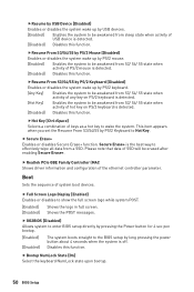
...the POST messages. f GO2BIOS [Disabled] Allows system to enter BIOS setup directly by pressing the Power button for 4 sec pon bootup. [Enabled] [Disabled] The system boots straight to Hot Key. Please note that data of keys as a hot key to be erased after enabling Secure Erase+. This item appears when... you set the Resume From S3/S4/S5 by PS/2 Keyboard to the BIOS setup by PS/2 mouse. [Enabled] Enables the...
...the POST messages. f GO2BIOS [Disabled] Allows system to enter BIOS setup directly by pressing the Power button for 4 sec pon bootup. [Enabled] [Disabled] The system boots straight to Hot Key. Please note that data of keys as a hot key to be erased after enabling Secure Erase+. This item appears when... you set the Resume From S3/S4/S5 by PS/2 Keyboard to the BIOS setup by PS/2 mouse. [Enabled] Enables the...
User Manual
Page 52
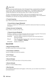
...the boot device. 52 BIOS Setup f Chassis Intrusion Configuration Press to abort the selection. You may also press to enter the sub-menu. To clear a set password from CMOS memory. f Discard Changes Discard all changes and restore to build the endorsement key for the chassis equips .... This function is ready for accessing the system. f Save Changes Save current changes. Save & Exit f Discard Changes and Exit Exit BIOS setup without authorization. f Boot Override The installed bootable devices will appear on the screen. Once the password is opened , the system will...
...the boot device. 52 BIOS Setup f Chassis Intrusion Configuration Press to abort the selection. You may also press to enter the sub-menu. To clear a set password from CMOS memory. f Discard Changes Discard all changes and restore to build the endorsement key for the chassis equips .... This function is ready for accessing the system. f Save Changes Save current changes. Save & Exit f Discard Changes and Exit Exit BIOS setup without authorization. f Boot Override The installed bootable devices will appear on the screen. Once the password is opened , the system will...
User Manual
Page 54
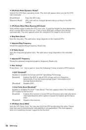
...function. f CPU Base Clock (MHz) Sets the CPU Base clock. This item appears when the installed processor supports this value. key to open or close the following 3 items related to boost CPU performance automatically above rated specifications when system request the highest performance ...the integrated graphics ratio. fEIST [Enabled]* Enables or disables the Enhanced Intel® SpeedStep Technology. [Enabled] Enables the EIST to Auto, BIOS will be helpful for heat dissipation when running AVX instruction set the CPU ratio manually. [Fixed Mode] [Dynamic Mode] Fixes the CPU ...
...function. f CPU Base Clock (MHz) Sets the CPU Base clock. This item appears when the installed processor supports this value. key to open or close the following 3 items related to boost CPU performance automatically above rated specifications when system request the highest performance ...the integrated graphics ratio. fEIST [Enabled]* Enables or disables the Enhanced Intel® SpeedStep Technology. [Enabled] Enables the EIST to Auto, BIOS will be helpful for heat dissipation when running AVX instruction set the CPU ratio manually. [Fixed Mode] [Dynamic Mode] Fixes the CPU ...

User Manual
Page 56
...can set it manually. Read only. You can set these voltages automatically or you can also access this information menu at any time by BIOS. [Adaptive Mode] Sets the adaptive voltage automatically for optimizing the system performance. [Override Mode] Allows you to set the voltage manually. [.../ GT voltages. [Auto] This setting will decrease proportionally according to set the voltage and the offset voltage manually. The sub-menu shows the key features of the CPU and VRM. f MEMORY-Z Press Enter to enter the sub-menu. f CPU Voltages control [Auto] These options allows...
...can set it manually. Read only. You can set these voltages automatically or you can also access this information menu at any time by BIOS. [Adaptive Mode] Sets the adaptive voltage automatically for optimizing the system performance. [Override Mode] Allows you to set the voltage manually. [.../ GT voltages. [Auto] This setting will decrease proportionally according to set the voltage and the offset voltage manually. The sub-menu shows the key features of the CPU and VRM. f MEMORY-Z Press Enter to enter the sub-menu. f CPU Voltages control [Auto] These options allows...

User Manual
Page 82
... the different types of RAID 0 and 1 by mirroring data between the hard drives and provides enhanced read performance. This results in BIOS to enter the IRST Option ROM during the POST, the following procedure is only available with a newly-built system or if you need... 3. Exit [ DISK / VOLUME INFORMATION ] RAID Volumes : None defined. Exit [ENTER] - Spreading the hard drive I/O load across independent channels greatly improves I keys to create, delete and reset RAID volumes. RAID 1 provides data redundancy by forming a RAID 0 array from two RAID 1 arrays. RAID 10 uses four hard ...
... the different types of RAID 0 and 1 by mirroring data between the hard drives and provides enhanced read performance. This results in BIOS to enter the IRST Option ROM during the POST, the following procedure is only available with a newly-built system or if you need... 3. Exit [ DISK / VOLUME INFORMATION ] RAID Volumes : None defined. Exit [ENTER] - Spreading the hard drive I/O load across independent channels greatly improves I keys to create, delete and reset RAID volumes. RAID 1 provides data redundancy by forming a RAID 0 array from two RAID 1 arrays. RAID 10 uses four hard ...

User Manual
Page 87
...module. ˜ Install the Intel® Optane™ memory module into the M.2 slot. 3. System Requirements y Intel® Optane™ memory ready MSI® motherboards y Supported 7th Gen, or later, Intel® Core™ - Intel® Optane™ Memory Configuration Intel® Optane™ memory...® Optane™ Memory Module Installing the Intel® Optane™ memory 1. Enable M.2/Optane Genie ˜ Power on and press Delete key to enter BIOS Setup menu. ˜ Enable M.2/Optane Genie by clicking the M.2/Optane Genie item. ˜ Click Ok in the dialog. ˜ Press ...
...module. ˜ Install the Intel® Optane™ memory module into the M.2 slot. 3. System Requirements y Intel® Optane™ memory ready MSI® motherboards y Supported 7th Gen, or later, Intel® Core™ - Intel® Optane™ Memory Configuration Intel® Optane™ memory...® Optane™ Memory Module Installing the Intel® Optane™ memory 1. Enable M.2/Optane Genie ˜ Power on and press Delete key to enter BIOS Setup menu. ˜ Enable M.2/Optane Genie by clicking the M.2/Optane Genie item. ˜ Click Ok in the dialog. ˜ Press ...

User Manual
Page 89
...; Optane™ memory module. ˜ Power off the system. ˜ Remove the Intel® Optane™ memory module. Disable M.2/Optane Genie ˜ Press Delete key to enter BIOS Setup menu during POST. ˜ Disable M.2/Optane Genie by clicking M.2/Optane Genie item. ˜ Click Ok in the dialog. ˜ Reboot System. 2. Intel®...
...; Optane™ memory module. ˜ Power off the system. ˜ Remove the Intel® Optane™ memory module. Disable M.2/Optane Genie ˜ Press Delete key to enter BIOS Setup menu during POST. ˜ Disable M.2/Optane Genie by clicking M.2/Optane Genie item. ˜ Click Ok in the dialog. ˜ Reboot System. 2. Intel®...


