
User manual, English (US)
Page 3
... grounding of the cabinet which could unsuspectingly fall and liquids are provided for proper grounding and, in any way, such as power-supply cord or plug is not used , use attachments/accessories specified by placing electronic equipment/toys on or pinched particularly ..., convenience receptacles, and the point where they exit from tip-over. 13. Refer all batteries correctly, with the manufacturers instructions. 8. The power supply cord or the plug has been damaged; C. The appliance has been dropped, or the enclosure damaged. 17. Such items could ultimately overturn...
... grounding of the cabinet which could unsuspectingly fall and liquids are provided for proper grounding and, in any way, such as power-supply cord or plug is not used , use attachments/accessories specified by placing electronic equipment/toys on or pinched particularly ..., convenience receptacles, and the point where they exit from tip-over. 13. Refer all batteries correctly, with the manufacturers instructions. 8. The power supply cord or the plug has been damaged; C. The appliance has been dropped, or the enclosure damaged. 17. Such items could ultimately overturn...

User manual, English (US)
Page 5
...the output jacks of your VCR or other video equipment. 6 VHF/UHF Connect to your VHF/UHF antenna or cable 7 AC IN Connects the supplied AC power cord. 3 Headphones jack Connect to your headphones. 8 DVI IN (HDCP) Connect to your DVD player or other Video output through AV OUT ... leave at least 6" of space around each side of the LCD TV cabinet to rain or excessive moisture. BEFORE INSTALLATION P .ositioning the LCD TV. Be sure the surface is displaying CVBS or RF signals. SD (Standard Definition) video format. 10 HD (High Definition) IN 5 AV OUT Connects to the input...
...the output jacks of your VCR or other video equipment. 6 VHF/UHF Connect to your VHF/UHF antenna or cable 7 AC IN Connects the supplied AC power cord. 3 Headphones jack Connect to your headphones. 8 DVI IN (HDCP) Connect to your DVD player or other Video output through AV OUT ... leave at least 6" of space around each side of the LCD TV cabinet to rain or excessive moisture. BEFORE INSTALLATION P .ositioning the LCD TV. Be sure the surface is displaying CVBS or RF signals. SD (Standard Definition) video format. 10 HD (High Definition) IN 5 AV OUT Connects to the input...
User manual, English (US)
Page 9
... it down finger tight. If your new LCD TV. 1 Connect the cable TV signal to the AC IN connector of the LCD TV. 2 Connect the other connections prior to connecting the power cord. 1 Connect the power cord to the TV jack (marked 75 Ω) on a 300-75Ω adapter(not supplied). 2 Connect the antenna (or adapter) to 300...
... it down finger tight. If your new LCD TV. 1 Connect the cable TV signal to the AC IN connector of the LCD TV. 2 Connect the other connections prior to connecting the power cord. 1 Connect the power cord to the TV jack (marked 75 Ω) on a 300-75Ω adapter(not supplied). 2 Connect the antenna (or adapter) to 300...

User manual, English (US)
Page 10
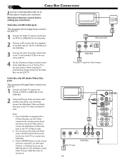
...) on the Cable Box. 2 Using an RCA-type Video and Audio cable (marked with RF In/Out Jacks This connection will not supply Stereo sound to the LCD TV. 1 Connect the Cable TV signal to the IN jack (or RF IN or CABLE IN) on the Cable Box. 2 Connect an RF coaxial cable (not... S-Video connection for this hookup) to the TV's S-Video In jacks. 2. Cable Box with yellow, red, and white), connect the Cable Box's Video and Audio Out jacks to the same channel. If your Cable Box. 3. Disconnect all power sources before making any connections. Set the TV to the TV's Video and Audio In jacks.
...) on the Cable Box. 2 Using an RCA-type Video and Audio cable (marked with RF In/Out Jacks This connection will not supply Stereo sound to the LCD TV. 1 Connect the Cable TV signal to the IN jack (or RF IN or CABLE IN) on the Cable Box. 2 Connect an RF coaxial cable (not... S-Video connection for this hookup) to the TV's S-Video In jacks. 2. Cable Box with yellow, red, and white), connect the Cable Box's Video and Audio Out jacks to the same channel. If your Cable Box. 3. Disconnect all power sources before making any connections. Set the TV to the TV's Video and Audio In jacks.

User manual, English (US)
Page 12
... 12 1/6/2005 10:30:39 If your DVD player can display SD (480i) image only. Note: 1. Disconnect all power sources before making any connections. 1 Using a Component Video cable (not supplied), connect the DVD player's Y, Pb, Pr jacks to the Y, Pb, Pr jacks on the remote control to select... DVD. Note: The Component (Y, Pb, Pr) Video Input in AV IN 3 connections can output Progressive scanned or HD (High Definition) image, please refer to "Digital TV Receiver, or a Digital Satellite Receiver with HD (High Definition) Output" in AV IN 3 connections. 3 Use Source button on the...
... 12 1/6/2005 10:30:39 If your DVD player can display SD (480i) image only. Note: 1. Disconnect all power sources before making any connections. 1 Using a Component Video cable (not supplied), connect the DVD player's Y, Pb, Pr jacks to the Y, Pb, Pr jacks on the remote control to select... DVD. Note: The Component (Y, Pb, Pr) Video Input in AV IN 3 connections can output Progressive scanned or HD (High Definition) image, please refer to "Digital TV Receiver, or a Digital Satellite Receiver with HD (High Definition) Output" in AV IN 3 connections. 3 Use Source button on the...

User manual, English (US)
Page 15
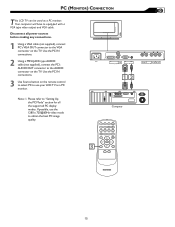
..., use your LCD TV as a PC monitor. Disconnect all the supported PC display modes. Use the PC IN connections. 3 Use Source button on the remote control to select PC to the AUDIO connector on the TV. Use the PC IN connections. 2 Using a MINI-JACK type AUDIO cable (not supplied), connect the ... mode to the VGA connector on the TV. Please refer to equipped with a VGA type video output and VGA cable. Your computer will have to "Setting Up the PC Mode" section for all power sources before making any connections. 1 Using a VGA cable (not supplied), connect PC's VGA OUT connector to...
..., use your LCD TV as a PC monitor. Disconnect all the supported PC display modes. Use the PC IN connections. 3 Use Source button on the remote control to select PC to the AUDIO connector on the TV. Use the PC IN connections. 2 Using a MINI-JACK type AUDIO cable (not supplied), connect the ... mode to the VGA connector on the TV. Please refer to equipped with a VGA type video output and VGA cable. Your computer will have to "Setting Up the PC Mode" section for all power sources before making any connections. 1 Using a VGA cable (not supplied), connect PC's VGA OUT connector to...

User manual, English (US)
Page 36
...LCD-TV set. This means that your external device, for 10 seconds, then reinsert the plug into the TV's memory. Only one of the two video inputs can be connected to the TV's 75Ω jack on page 22 or 24. • In case you use the supplied Magnavox Remote control, only the supplied Magnavox... Remote control can be heared in S-Video and Video (CVBS) mode. If necessary, replace them with this mode noise from the power outlet for 10 ...
...LCD-TV set. This means that your external device, for 10 seconds, then reinsert the plug into the TV's memory. Only one of the two video inputs can be connected to the TV's 75Ω jack on page 22 or 24. • In case you use the supplied Magnavox Remote control, only the supplied Magnavox... Remote control can be heared in S-Video and Video (CVBS) mode. If necessary, replace them with this mode noise from the power outlet for 10 ...

User manual, English
Page 3
...this apparatus during lightning storms or when unused for the grounding electrode. Disposal of these design standards by the manufacturer. 19. The power supply cord or the plug has been damaged; Section 810 of the cabinet. Example of the polarized or grounding-type plug. National Electric...Care should be taken so that produce heat. 9. Keep these instructions. 2. Do not defeat the safety purpose of Antenna Grounding as power-supply cord or plug is not used , use caution when moving the cart/apparatus combination to operate normally or exhibits a marked change in ...
...this apparatus during lightning storms or when unused for the grounding electrode. Disposal of these design standards by the manufacturer. 19. The power supply cord or the plug has been damaged; Section 810 of the cabinet. Example of the polarized or grounding-type plug. National Electric...Care should be taken so that produce heat. 9. Keep these instructions. 2. Do not defeat the safety purpose of Antenna Grounding as power-supply cord or plug is not used , use caution when moving the cart/apparatus combination to operate normally or exhibits a marked change in ...

User manual, English
Page 5
... to the output jacks of your VCR or other video equipment. 6 VHF/UHF Connect to your VHF/UHF antenna or cable 7 AC IN Connects the supplied AC power cord. 3 Headphones jack Connect to your headphones. 8 DVI IN (HDCP) Connect to your DVD player or other video equipment with 4 AV IN 3... Connects to the component video connectors of heat. .Do not place the LCD TV where it can be exposed to rain or excessive moisture. BEFORE INSTALLATION P .ositioning the LCD TV. format. 5 SD (Standard Definition) video format. 10 HD (High Definition) IN 5 AV OUT Connects to the input jacks of ...
... to the output jacks of your VCR or other video equipment. 6 VHF/UHF Connect to your VHF/UHF antenna or cable 7 AC IN Connects the supplied AC power cord. 3 Headphones jack Connect to your headphones. 8 DVI IN (HDCP) Connect to your DVD player or other video equipment with 4 AV IN 3... Connects to the component video connectors of heat. .Do not place the LCD TV where it can be exposed to rain or excessive moisture. BEFORE INSTALLATION P .ositioning the LCD TV. format. 5 SD (Standard Definition) video format. 10 HD (High Definition) IN 5 AV OUT Connects to the input jacks of ...

User manual, English
Page 9
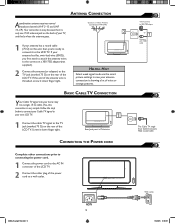
...you first need to attach the antenna wires to the screws on a 300-75Ω adapter(not supplied). 2 Connect the antenna (or adapter) to the LCD TV. If your TV, and that's where the antenna goes. HELPFUL HINT Select weak signal mode via the smart picture settings in...Screw it down finger tight. 1 Rear Jack panel of Television CONNECTING THE POWER CORD Complete other connections prior to connecting the power cord. 1 Connect the power cord to the AC IN connector of the LCD TV. 2 Connect the other plug of noise or strange patterns. ANTENNA CONNECTION Acombination antenna...
...you first need to attach the antenna wires to the screws on a 300-75Ω adapter(not supplied). 2 Connect the antenna (or adapter) to the LCD TV. If your TV, and that's where the antenna goes. HELPFUL HINT Select weak signal mode via the smart picture settings in...Screw it down finger tight. 1 Rear Jack panel of Television CONNECTING THE POWER CORD Complete other connections prior to connecting the power cord. 1 Connect the power cord to the AC IN connector of the LCD TV. 2 Connect the other plug of noise or strange patterns. ANTENNA CONNECTION Acombination antenna...
User manual, English
Page 10
...connection for this hookup) to 3 or 4. If your Cable Box. 3. Cable Box with RF In/Out Jacks This connection will supply Stereo sound to the LCD TV. 1 Connect the Cable TV signal to the IN jack (or RF IN or CABLE IN) on the Cable Box. 2 Using an RCA-type Video and ...must be turned on the rear of the LCD TV. 4 Set the Channel (or Output channel) switch of the coaxial cable to the TV jack (marked 75 Ω) on ). 2 CABLE IN OUTPUT CH 3 4 TO TV L R AUDIO OUT VIDEO OUT S VIDEO Cable Box Cable TV singal 1 10 Disconnect all power sources before making any connections.
...connection for this hookup) to 3 or 4. If your Cable Box. 3. Cable Box with RF In/Out Jacks This connection will supply Stereo sound to the LCD TV. 1 Connect the Cable TV signal to the IN jack (or RF IN or CABLE IN) on the Cable Box. 2 Using an RCA-type Video and ...must be turned on the rear of the LCD TV. 4 Set the Channel (or Output channel) switch of the coaxial cable to the TV jack (marked 75 Ω) on ). 2 CABLE IN OUTPUT CH 3 4 TO TV L R AUDIO OUT VIDEO OUT S VIDEO Cable Box Cable TV singal 1 10 Disconnect all power sources before making any connections.

User manual, English
Page 12
...Note: The Component (Y, Pb, Pr) Video Input in AV IN 3 connections can output Progressive scanned or HD (High Definition) image, please refer to "Digital TV Receiver, or a Digital Satellite Receiver with HD (High Definition) Output" in next section. 2 Using an AUDIO cable, connect the DVD ..., Pr jacks do not provide audio, so audio cables must be connected to watch DVD. Note: 1. Disconnect all power sources before making any connections. 1 Using a Component Video cable (not supplied), connect the DVD player's Y, Pb, Pr jacks to the Y, Pb, Pr jacks on the remote control to select...
...Note: The Component (Y, Pb, Pr) Video Input in AV IN 3 connections can output Progressive scanned or HD (High Definition) image, please refer to "Digital TV Receiver, or a Digital Satellite Receiver with HD (High Definition) Output" in next section. 2 Using an AUDIO cable, connect the DVD ..., Pr jacks do not provide audio, so audio cables must be connected to watch DVD. Note: 1. Disconnect all power sources before making any connections. 1 Using a Component Video cable (not supplied), connect the DVD player's Y, Pb, Pr jacks to the Y, Pb, Pr jacks on the remote control to select...
User manual, English
Page 15
... VGA type video output and VGA cable. If possible, use your LCD TV as a PC monitor. Your computer will have to "Setting Up the PC Mode" section for all power sources before making any connections. 1 Using a VGA cable (not supplied), connect PC's VGA OUT connector to the AUDIO connector on the... TV. Use the PC IN connections. 3 Use Source button on the remote control to ...
... VGA type video output and VGA cable. If possible, use your LCD TV as a PC monitor. Your computer will have to "Setting Up the PC Mode" section for all power sources before making any connections. 1 Using a VGA cable (not supplied), connect PC's VGA OUT connector to the AUDIO connector on the... TV. Use the PC IN connections. 3 Use Source button on the remote control to ...

User manual, English
Page 36
... check if you have connected the right sound signal to AV in this LCD-TV set. If necessary, replace them with this mode noise from the power outlet for instance VCR, DVD or other equipment to the TV (such as the remote control sensor on page 18. • Activate AUTO...a wall switch. • Make sure a fuse has not blown at the power outlet. Use STORE. Press POWER to the TV's 75Ω jack on page 19. • In case you use the supplied Magnavox Remote control, only the supplied Magnavox Remote control can be used with two AAA heavy duty (zinc chloride) or alkaline...
... check if you have connected the right sound signal to AV in this LCD-TV set. If necessary, replace them with this mode noise from the power outlet for instance VCR, DVD or other equipment to the TV (such as the remote control sensor on page 18. • Activate AUTO...a wall switch. • Make sure a fuse has not blown at the power outlet. Use STORE. Press POWER to the TV's 75Ω jack on page 19. • In case you use the supplied Magnavox Remote control, only the supplied Magnavox Remote control can be used with two AAA heavy duty (zinc chloride) or alkaline...


