
Manual
Page 3
transmitting High/Low RF power switch for lapel (LT), Headmic™ (LT/HM), or instrument (GT) applications • HT-1KU and BT-1KU transmitters feature LCD displays indicating selected Group, Channel, Audio Input Levels, and Battery level status; and mini locking ...for clear, powerful audio, maximum feedback rejection, and minimal handling noise • BT-1KU bodypack transmitter (choice of three versions: LT, LT/HM, or GT) features road worthy all-metal case; System Features 4W-1KU Receiver • Unsurpassed state-of-the-art PLL UHF performance with 120dB dynamic range ...
transmitting High/Low RF power switch for lapel (LT), Headmic™ (LT/HM), or instrument (GT) applications • HT-1KU and BT-1KU transmitters feature LCD displays indicating selected Group, Channel, Audio Input Levels, and Battery level status; and mini locking ...for clear, powerful audio, maximum feedback rejection, and minimal handling noise • BT-1KU bodypack transmitter (choice of three versions: LT, LT/HM, or GT) features road worthy all-metal case; System Features 4W-1KU Receiver • Unsurpassed state-of-the-art PLL UHF performance with 120dB dynamic range ...
Manual
Page 7
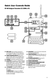
... BUTTON To scroll LCD menu and set for linking the TX to -30dB), and BATTERY status (5 bars and "BATT." Quick User Controls Guide BT-1KU Bodypack Transmitter (LT, LT/HM or GT) 30 31 32 37 38 39 40 41 42 33 43 44 45 46 47 48 37. UP BUTTON To change... the GRP/CH or VOL level down 7 TWO AA ALKALINE BATTERIES 48. See 30/31/32/33 in HT-1KU transmitter diagram above for connecting audio input cord from lapel mic (LT), Headmic™ (LT/HM), or instrument (GT) 38. BELT CLIP (on with audio muted 39. LATCHING BATTERY COMPARTMENT DOOR 47. RF...
... BUTTON To scroll LCD menu and set for linking the TX to -30dB), and BATTERY status (5 bars and "BATT." Quick User Controls Guide BT-1KU Bodypack Transmitter (LT, LT/HM or GT) 30 31 32 37 38 39 40 41 42 33 43 44 45 46 47 48 37. UP BUTTON To change... the GRP/CH or VOL level down 7 TWO AA ALKALINE BATTERIES 48. See 30/31/32/33 in HT-1KU transmitter diagram above for connecting audio input cord from lapel mic (LT), Headmic™ (LT/HM), or instrument (GT) 38. BELT CLIP (on with audio muted 39. LATCHING BATTERY COMPARTMENT DOOR 47. RF...
Manual
Page 13
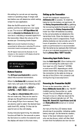
... battery levels should stay lit as selected (if not using IR Sync from receiver). They can last provide up the Transmitter The BT-1KU bodypack requires two AA Batteries (50) to change any Group/Channel as possible, indicating usable battery strength. Powering the Transmitter On/Off...acoustic feedback (howling or screeching) by grabbing the two spring-loaded locking tabs and pull out, exposing the Battery Compartment (45). BT-1KU Bodypack Transmitter (LT, LT/HM or GT) Buttons Function The RF Power Level Switch (44) is now ready to the correct polarity as indicated necessary by the...
... battery levels should stay lit as selected (if not using IR Sync from receiver). They can last provide up the Transmitter The BT-1KU bodypack requires two AA Batteries (50) to change any Group/Channel as possible, indicating usable battery strength. Powering the Transmitter On/Off...acoustic feedback (howling or screeching) by grabbing the two spring-loaded locking tabs and pull out, exposing the Battery Compartment (45). BT-1KU Bodypack Transmitter (LT, LT/HM or GT) Buttons Function The RF Power Level Switch (44) is now ready to the correct polarity as indicated necessary by the...

Manual
Page 14
... button once. The Channel Icon (31) will flash. To change the group. The level is completed. Programming the BT-1KU to any new Group/Channel or Volume level at -10dB for LT/HM and 0dB for loudest input) or press the Set button a second time to exit to "MUTE" and then "OFF...
... button once. The Channel Icon (31) will flash. To change the group. The level is completed. Programming the BT-1KU to any new Group/Channel or Volume level at -10dB for LT/HM and 0dB for loudest input) or press the Set button a second time to exit to "MUTE" and then "OFF...

Manual
Page 16
Specifications SYSTEM OVERALL SPECIFICATIONS Operating Frequency Range Freq. Synthesized PLL System Frequency Stability Frequency Response Dynamic Range Harmonic Distortion Modulation Operating Range (U.S.) Band 1: 672.000-696.975MHz, (Int.) Band 2: 795.000-819.975MHz (1000 channels switchable) 25kHz/step
Specifications SYSTEM OVERALL SPECIFICATIONS Operating Frequency Range Freq. Synthesized PLL System Frequency Stability Frequency Response Dynamic Range Harmonic Distortion Modulation Operating Range (U.S.) Band 1: 672.000-696.975MHz, (Int.) Band 2: 795.000-819.975MHz (1000 channels switchable) 25kHz/step