
Owner Manual
Page 1
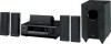
...before making connections and plugging in this manual for purchasing an Onkyo 5.1ch Home Theater System. Please retain this manual will enable you for future reference. 5.1ch Home Theater System HT-S3100 HT-S3105 AV Receiver (HT-R340) Speaker Package HTP-360 (North American and Asian models)... HTP-318 (European models) Instruction Manual Thank you to obtain optimum performance and listening enjoyment from your AV components ....... 39 Using the Tuner...
...before making connections and plugging in this manual for purchasing an Onkyo 5.1ch Home Theater System. Please retain this manual will enable you for future reference. 5.1ch Home Theater System HT-S3100 HT-S3105 AV Receiver (HT-R340) Speaker Package HTP-360 (North American and Asian models)... HTP-318 (European models) Instruction Manual Thank you to obtain optimum performance and listening enjoyment from your AV components ....... 39 Using the Tuner...

Owner Manual
Page 4
... monitors are magnetically sensitive devices and as such are likely to suffer discoloration or picture distortion when conventional speakers are required, the AV receiver must approved by ASTA or BSI to BS1362 and have no batteries are placed nearby. Input Signal Warning The speakers can ...64257;er, bathroom, or kitchen. • Do not put it back on the plug. Check for normal music reproduction. MIYAGI ONKYO EUROPE ELECTRONICS GmbH Memory Backup The AV receiver uses a battery-less memory backup system in your TV or monitor. Although no magnetic shield. Putting them , even if...
... monitors are magnetically sensitive devices and as such are likely to suffer discoloration or picture distortion when conventional speakers are required, the AV receiver must approved by ASTA or BSI to BS1362 and have no batteries are placed nearby. Input Signal Warning The speakers can ...64257;er, bathroom, or kitchen. • Do not put it back on the plug. Check for normal music reproduction. MIYAGI ONKYO EUROPE ELECTRONICS GmbH Memory Backup The AV receiver uses a battery-less memory backup system in your TV or monitor. Although no magnetic shield. Putting them , even if...
Owner Manual
Page 5
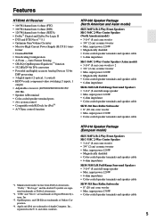
... Surround Speakers • 3-1/4" (8 cm) full-range speaker • Max. "DTS" and "Neo:6" are trademarks of Digital Theater Systems, Inc. *3. Features HT-R340 AV Receiver • 100 W/channel into 6 ohms (FTC) • 100 W/channel into 6 ohms (DIN) • 120 W/channel into 6 ohms (JEITA... Laboratories. former • CinemaFILTER • Non-Scaling Configuration • A-Form - OptiResponse, and OR-EQ are trademarks of Onkyo Corporation. *4. input power:130 W • Color-coded speaker terminals and speaker cable HTP-318 Speaker Package (European model) SKF-318F ...
... Surround Speakers • 3-1/4" (8 cm) full-range speaker • Max. "DTS" and "Neo:6" are trademarks of Digital Theater Systems, Inc. *3. Features HT-R340 AV Receiver • 100 W/channel into 6 ohms (FTC) • 100 W/channel into 6 ohms (DIN) • 120 W/channel into 6 ohms (JEITA... Laboratories. former • CinemaFILTER • Non-Scaling Configuration • A-Form - OptiResponse, and OR-EQ are trademarks of Onkyo Corporation. *4. input power:130 W • Color-coded speaker terminals and speaker cable HTP-318 Speaker Package (European model) SKF-318F ...

Owner Manual
Page 6
... the Listening Modes 49 Advanced Operation Adjusting the Listening Modes 51 Advanced Setup 53 Troubleshooting 58 If you have the following items: AV Receiver HT-R340 HT-R340 Remote controller & two batteries (AA/R6) (American type shown) Indoor FM antenna (Connector type varies from country to country....) * In catalogs and on the AV receiver's power cord. (Adapter varies from country to country.) AM loop antenna Power-plug adapter Only supplied...
... the Listening Modes 49 Advanced Operation Adjusting the Listening Modes 51 Advanced Setup 53 Troubleshooting 58 If you have the following items: AV Receiver HT-R340 HT-R340 Remote controller & two batteries (AA/R6) (American type shown) Indoor FM antenna (Connector type varies from country to country....) * In catalogs and on the AV receiver's power cord. (Adapter varies from country to country.) AM loop antenna Power-plug adapter Only supplied...

Owner Manual
Page 8
... RT/PTY/TP button (44, 45) This button is the RT/PTY/TP button, and it flashes while a signal is used to set the AV receiver to On or Standby. On the European model, this is used to select the Stereo listening mode. See "Using RDS (European models only)" on..." on page 43. A STANDBY/ON button (37) This button is being received from the remote controller. B STANDBY indicator (37) This indicator lights up when the AV receiver is in parentheses.
... RT/PTY/TP button (44, 45) This button is the RT/PTY/TP button, and it flashes while a signal is used to set the AV receiver to On or Standby. On the European model, this is used to select the Stereo listening mode. See "Using RDS (European models only)" on..." on page 43. A STANDBY/ON button (37) This button is being received from the remote controller. B STANDBY indicator (37) This indicator lights up when the AV receiver is in parentheses.

Owner Manual
Page 9
... 57) These indicators show the currently selected listening mode and digital audio format. 4 Tuning indicators TUNED (41): This indicator lights up when the AV Receiver is tuned to select radio presets (see pages 41, 42). Indicator B lights up when speaker set items. The ENTER button is selected, ...menus. AUTO (41): This indicator lights up when presetting radio stations. RDS (European model only) (43): This indicator lights up when the AV receiver is tuned to adjust the volume of stereo headphones for private listening. M MASTER VOLUME control (39) This control is used to adjust ...
... 57) These indicators show the currently selected listening mode and digital audio format. 4 Tuning indicators TUNED (41): This indicator lights up when the AV Receiver is tuned to select radio presets (see pages 41, 42). Indicator B lights up when speaker set items. The ENTER button is selected, ...menus. AUTO (41): This indicator lights up when presetting radio stations. RDS (European model only) (43): This indicator lights up when the AV receiver is tuned to adjust the volume of stereo headphones for private listening. M MASTER VOLUME control (39) This control is used to adjust ...

Owner Manual
Page 10
... a CD or DVD player and other component that component. 10 To use , you must make an analog audio connection (RCA) between the AV receiver and the other recorder with digital audio outputs. B COMPONENT VIDEO A DVD player, TV, or other components with analog inputs and outputs....(only some models) This voltage selector provides compatibility with a 5.1-channel analog output. J CD IN These analog inputs can be used to connect another Onkyo component. The VIDEO 2, VIDEO 3, composite video, and audio inputs can be used to connect a VCR. C AM ANTENNA These push terminals are for...
... a CD or DVD player and other component that component. 10 To use , you must make an analog audio connection (RCA) between the AV receiver and the other recorder with digital audio outputs. B COMPONENT VIDEO A DVD player, TV, or other components with analog inputs and outputs....(only some models) This voltage selector provides compatibility with a 5.1-channel analog output. J CD IN These analog inputs can be used to connect another Onkyo component. The VIDEO 2, VIDEO 3, composite video, and audio inputs can be used to connect a VCR. C AM ANTENNA These push terminals are for...

Owner Manual
Page 12
...Remote Controller Including the AV receiver, the remote controller can control an Onkyo DVD DVD player and CD/MD/CDR/HDD C D player/recorder. RECEIVER Mode RECEIVER mode is used to control up to control the component. To set the remote controller to control the AV receiver. DIMMER SLEEP CH...buttons supported by using the five REMOTE MODE buttons. ■ RECEIVER/TAPE Mode In RECEIVER/TAPE mode, you can control RECEIVER the AV receiver and an Onkyo cassette TAPE recorder connected via . ■ DVD, CD, MD, CDR & HDD Modes With these modes, you can be used to ...
...Remote Controller Including the AV receiver, the remote controller can control an Onkyo DVD DVD player and CD/MD/CDR/HDD C D player/recorder. RECEIVER Mode RECEIVER mode is used to control up to control the component. To set the remote controller to control the AV receiver. DIMMER SLEEP CH...buttons supported by using the five REMOTE MODE buttons. ■ RECEIVER/TAPE Mode In RECEIVER/TAPE mode, you can control RECEIVER the AV receiver and an Onkyo cassette TAPE recorder connected via . ■ DVD, CD, MD, CDR & HDD Modes With these modes, you can be used to ...

Owner Manual
Page 13
...sources. B INPUT SELECTOR buttons (39) These buttons are used to turn on the OptiResponse Equalizer, which optimizes performance when the HT-R340 is used to mute the AV receiver. C MULTI CH button (40) This button is used to select any of each speaker. button (42) This ... remote controller, the REMOTE MODE button for the currently selected mode lights up. D DIMMER button (45) This button is used to set the AV receiver to select the remote controller modes. STEREO button This button selects the Stereo listening mode. I LISTENING MODE buttons (49) These buttons can...
...sources. B INPUT SELECTOR buttons (39) These buttons are used to turn on the OptiResponse Equalizer, which optimizes performance when the HT-R340 is used to mute the AV receiver. C MULTI CH button (40) This button is used to select any of each speaker. button (42) This ... remote controller, the REMOTE MODE button for the currently selected mode lights up. D DIMMER button (45) This button is used to set the AV receiver to select the remote controller modes. STEREO button This button selects the Stereo listening mode. I LISTENING MODE buttons (49) These buttons can...

Owner Manual
Page 18
... be controlled. B Stop [ ] button This button is used to start fast forward. C Reverse Play [ ] button This button is used to control an Onkyo cassette recorder connected to the AV receiver via . DIMMER SLEEP CH DISC ALBUM VOL TOP MENU MENU SP A / B PLAYLIST ENTER MUTING PLAYLIST RETURN SETUP LISTENING MODE STEREO SURROUND AUDIO...
... be controlled. B Stop [ ] button This button is used to start fast forward. C Reverse Play [ ] button This button is used to control an Onkyo cassette recorder connected to the AV receiver via . DIMMER SLEEP CH DISC ALBUM VOL TOP MENU MENU SP A / B PLAYLIST ENTER MUTING PLAYLIST RETURN SETUP LISTENING MODE STEREO SURROUND AUDIO...

Owner Manual
Page 19
..., thereby draining the batteries. • The remote controller may not work if there's an obstacle between 220 and 240 volts, set it and the AV receiver's remote control sensor. 19 Keep this in mind when installing. • The remote controller will not work reliably if the... AV receiver is installed in the same room, or the AV receiver is installed close to equipment that the voltage selector is subjected to "220240V." If it's between it to bright light...
..., thereby draining the batteries. • The remote controller may not work if there's an obstacle between 220 and 240 volts, set it and the AV receiver's remote control sensor. 19 Keep this in mind when installing. • The remote controller will not work reliably if the... AV receiver is installed in the same room, or the AV receiver is installed close to equipment that the voltage selector is subjected to "220240V." If it's between it to bright light...

Owner Manual
Page 20
...Set B: 2 channels No sound Center speaker (SKC-360C) This speaker enhances the front left and right speakers (SKF-360F L/R) These output the overall sound. AV receiver A SPEAKERS B Remote controller or SP A / B Speaker set A On Off Speaker set B is to provide a solid anchor for precise sound positioning... movies it close to your main listening room for dialog. Position them inward. HTP-360 speaker package is shown 1/3 of speakers with the AV receiver: speaker set A and speaker set A is on , speaker set B. Their role in another room and offers 2-channel stereo playback...
...Set B: 2 channels No sound Center speaker (SKC-360C) This speaker enhances the front left and right speakers (SKF-360F L/R) These output the overall sound. AV receiver A SPEAKERS B Remote controller or SP A / B Speaker set A On Off Speaker set B is to provide a solid anchor for precise sound positioning... movies it close to your main listening room for dialog. Position them inward. HTP-360 speaker package is shown 1/3 of speakers with the AV receiver: speaker set A and speaker set A is on , speaker set B. Their role in another room and offers 2-channel stereo playback...

Owner Manual
Page 21
...8226; You can connect speakers with a lower impedance, and use speakers with an impedance of time, the built-in protection circuit may damage the AV receiver. • Don't connect more than one speaker to several terminals. Doing so may be activated. • Disconnect the power cord from... the ends of the speaker cables. (Supplied speaker cables are color-coded for a long period of 6 ohms or higher. Connecting Speaker The AV receiver's positive (+) speaker terminals are already stripped.) 2 While pressing the lever, insert the wire into the hole, and then release the lever....
...8226; You can connect speakers with a lower impedance, and use speakers with an impedance of time, the built-in protection circuit may damage the AV receiver. • Don't connect more than one speaker to several terminals. Doing so may be activated. • Disconnect the power cord from... the ends of the speaker cables. (Supplied speaker cables are color-coded for a long period of 6 ohms or higher. Connecting Speaker The AV receiver's positive (+) speaker terminals are already stripped.) 2 While pressing the lever, insert the wire into the hole, and then release the lever....

Owner Manual
Page 24
... commercially available outdoor FM antenna instead (see page 25). 24 If you must connect the antenna to achieve the best possible reception. The AV receiver won't pick up any radio signals without any antenna connected, so you cannot achieve good reception with thumbtacks or something similar. AM ...wires, not the insulation. Make sure that the wires are not polarity sensitive, so they can be connected either way around). Once your AV receiver, TV, speaker cables, and power cords. Connecting Antenna This section explains how to connect the supplied indoor FM antenna and AM loop...
... commercially available outdoor FM antenna instead (see page 25). 24 If you must connect the antenna to achieve the best possible reception. The AV receiver won't pick up any radio signals without any antenna connected, so you cannot achieve good reception with thumbtacks or something similar. AM ...wires, not the insulation. Make sure that the wires are not polarity sensitive, so they can be connected either way around). Once your AV receiver, TV, speaker cables, and power cords. Connecting Antenna This section explains how to connect the supplied indoor FM antenna and AM loop...

Owner Manual
Page 25
... antenna cable Notes: • Outdoor FM antennas work best when installed outside , but good results can sometimes be left connected. TV/FM antenna splitter To AV receiver To TV (or VCR) 25 Note that the AM loop antenna should be situated well away from possible noise sources, such as neon signs...
... antenna cable Notes: • Outdoor FM antennas work best when installed outside , but good results can sometimes be left connected. TV/FM antenna splitter To AV receiver To TV (or VCR) 25 Note that the AM loop antenna should be situated well away from possible noise sources, such as neon signs...

Owner Manual
Page 26
... malfunctions). • To prevent interference, keep audio and video cables away from power cords and speaker cables. Optical Digital Jacks The AV receiver's optical digital jack has shutter-type cover that open when an optical plug is the same as for optical. Caution: To... "L"). Left (white) Analog audio Left (white) Right (red) (Yellow) Composite video Right (red) (Yellow) • Push plugs in all AV components. Wrong! AV Cables & Jacks Video Component video cable Composite video cable Cable Y PB PR Jack Description Y Y PB PB PR PR Component video separates the luminance ...
... malfunctions). • To prevent interference, keep audio and video cables away from power cords and speaker cables. Optical Digital Jacks The AV receiver's optical digital jack has shutter-type cover that open when an optical plug is the same as for optical. Caution: To... "L"). Left (white) Analog audio Left (white) Right (red) (Yellow) Composite video Right (red) (Yellow) • Push plugs in all AV components. Wrong! AV Cables & Jacks Video Component video cable Composite video cable Cable Y PB PR Jack Description Y Y PB PB PR PR Component video separates the luminance ...

Owner Manual
Page 27
...must also connect it to the analog CD IN. For example, if you connect your DVD player to the AV receiver, you choose will be connected to the AV receiver using one for video. Connecting Your Components-Continued Connecting Both Audio & Video By connecting both the audio ... the appropriate input source on the formats supported by any composite video outputs. When choosing a connection format, bear in mind that the AV receiver doesn't convert between formats, so only outputs of your DVD player and other components. Audio equipment can be output by the COMPONENT...
...must also connect it to the analog CD IN. For example, if you connect your DVD player to the AV receiver, you choose will be connected to the AV receiver using one for video. Connecting Your Components-Continued Connecting Both Audio & Video By connecting both the audio ... the appropriate input source on the formats supported by any composite video outputs. When choosing a connection format, bear in mind that the AV receiver doesn't convert between formats, so only outputs of your DVD player and other components. Audio equipment can be output by the COMPONENT...

Owner Manual
Page 28
... Y PB PR VIDEO IN TV, projector, etc. B If your TV doesn't have component video input jacks, connect your DVD player to the AV receiver's COMPONENT VIDEO DVD IN jacks. HT-R340 BA B A B Y PB PR COMPONENT VIDEO OUT VIDEO OUT DVD player 28 : Signal Flow Connecting Your Components-Continued Connecting a DVD Player Step...
... Y PB PR VIDEO IN TV, projector, etc. B If your TV doesn't have component video input jacks, connect your DVD player to the AV receiver's COMPONENT VIDEO DVD IN jacks. HT-R340 BA B A B Y PB PR COMPONENT VIDEO OUT VIDEO OUT DVD player 28 : Signal Flow Connecting Your Components-Continued Connecting a DVD Player Step...

Owner Manual
Page 29
... listening modes with this connection. HT-R340 b a c d d cd d OPTICAL OUT COAXIAL OUT L R AUDIO OUT L R FRONT L R SURROUND SUB WOOFER CENTER Multichannel Connection : Signal Flow DVD player 29 IAL jack. Coaxial connections perform the same as optical ones. c Optionally, connecting your DVD player's audio out L/R jacks to the AV receiver's DVD IN FRONT L/R jacks...
... listening modes with this connection. HT-R340 b a c d d cd d OPTICAL OUT COAXIAL OUT L R AUDIO OUT L R FRONT L R SURROUND SUB WOOFER CENTER Multichannel Connection : Signal Flow DVD player 29 IAL jack. Coaxial connections perform the same as optical ones. c Optionally, connecting your DVD player's audio out L/R jacks to the AV receiver's DVD IN FRONT L/R jacks...

Owner Manual
Page 30
...) to your VCR's antenna input, and connect your VCR's antenna output jack to the AV receiver's VIDEO 1 IN L/R jacks. Step 2: Audio Connection a Connect your VCR's audio output jacks to your TV's antenna input jack. Antenna input (e.g., RF IN) HT-R340 B A C Coaxial feed B A Coaxial feed from TV antenna or set-top box a C Y PB...
...) to your VCR's antenna input, and connect your VCR's antenna output jack to the AV receiver's VIDEO 1 IN L/R jacks. Step 2: Audio Connection a Connect your VCR's audio output jacks to your TV's antenna input jack. Antenna input (e.g., RF IN) HT-R340 B A C Coaxial feed B A Coaxial feed from TV antenna or set-top box a C Y PB...