
Owner Manual
Page 1
...Onkyo AV Receiver. Contents Introduction 2 Connection 18 Turning On & First Time Setup .....48 Basic Operations 67 Using the Listening Modes ........81 Advanced Setup 92 NET/USB 120 Multi Zone 130 Controlling Other Components....139 Others 154 En Please retain this manual will enable you for future reference. AV Receiver TX-NR3007 TX...-NR5007 Instruction Manual Thank you to obtain optimum performance and listening enjoyment from your new AV Receiver. Following the instructions in the unit.
...Onkyo AV Receiver. Contents Introduction 2 Connection 18 Turning On & First Time Setup .....48 Basic Operations 67 Using the Listening Modes ........81 Advanced Setup 92 NET/USB 120 Multi Zone 130 Controlling Other Components....139 Others 154 En Please retain this manual will enable you for future reference. AV Receiver TX-NR3007 TX...-NR5007 Instruction Manual Thank you to obtain optimum performance and listening enjoyment from your new AV Receiver. Following the instructions in the unit.

Owner Manual
Page 3
.... The power cord plug is illegal without the permission of the following measures: • Reorient or relocate the receiving antenna. • Increase the separation between the equipment and receiver. • Connect the equipment into an outlet on the case. • This unit's top and rear panels...accordance with the limits for help. cian for a Class B digital device, pursuant to disconnect this unit or its power cord while your Onkyo dealer. 3. This equipment generates, uses and can radiate radio frequency energy and, if not installed and used to Part 15 of mild ...
.... The power cord plug is illegal without the permission of the following measures: • Reorient or relocate the receiving antenna. • Increase the separation between the equipment and receiver. • Connect the equipment into an outlet on the case. • This unit's top and rear panels...accordance with the limits for help. cian for a Class B digital device, pursuant to disconnect this unit or its power cord while your Onkyo dealer. 3. This equipment generates, uses and can radiate radio frequency energy and, if not installed and used to Part 15 of mild ...
Owner Manual
Page 4
... SP-B/ZONE2 RIGHT SP-B/ZONE2 RIGHT * In catalogs and on the body of the fuse. For European Models Declaration of Conformity We, ONKYO EUROPE ELECTRONICS GmbH LIEGNITZERSTRASSE 6, 82194 GROEBENZELL, GERMANY declare in own responsibility, that indicated on the power supply cord of this adapter if ...is not supplied for this apparatus may not correspond with the coloured markings identifying the terminals in compliance with the plug on the AV receiver's power cord (adapter varies from country to the terminal which is fitted with an appropriate fuse. Fit a suitable fuse in certain ...
... SP-B/ZONE2 RIGHT SP-B/ZONE2 RIGHT * In catalogs and on the body of the fuse. For European Models Declaration of Conformity We, ONKYO EUROPE ELECTRONICS GmbH LIEGNITZERSTRASSE 6, 82194 GROEBENZELL, GERMANY declare in own responsibility, that indicated on the power supply cord of this adapter if ...is not supplied for this apparatus may not correspond with the coloured markings identifying the terminals in compliance with the plug on the AV receiver's power cord (adapter varies from country to the terminal which is fitted with an appropriate fuse. Fit a suitable fuse in certain ...

Owner Manual
Page 5
...139 Preprogrammed Remote Control Codes 139 Looking up for Remote Control Code 139 Entering Remote Control Codes 141 Remote Control Codes for Onkyo Components Connected via V 142 Resetting REMOTE MODE Buttons 142 Resetting the Remote Controller 142 Controlling a TV 143 Controlling a ...Recorder 149 Activities Setup 150 Learning Commands 152 Using Normal Macros 153 Others Troubleshooting 154 Specifications (TX-NR3007 160 Specifications (TX-NR5007 161 Video Resolution Chart 162 * To reset the AV receiver to its factory defaults, turn it on and, while holding down the [VCR/DVR] button...
...139 Preprogrammed Remote Control Codes 139 Looking up for Remote Control Code 139 Entering Remote Control Codes 141 Remote Control Codes for Onkyo Components Connected via V 142 Resetting REMOTE MODE Buttons 142 Resetting the Remote Controller 142 Controlling a TV 143 Controlling a ...Recorder 149 Activities Setup 150 Learning Commands 152 Using Normal Macros 153 Others Troubleshooting 154 Specifications (TX-NR3007 160 Specifications (TX-NR5007 161 Video Resolution Chart 162 * To reset the AV receiver to its factory defaults, turn it on and, while holding down the [VCR/DVR] button...

Owner Manual
Page 7
... the THX Ultra2 Plus logo, which is a registered trademark of Apple Inc., registered in Alaska and Hawaii. *9. U.S. THX Ultra2 Plus receivers also feature proprietary THX technologies (e.g., THX Mode) which may apply. XM tuners and home docks or SIRIUS tuners (each sold separately. Use... of this copyright protection technology must install an Onkyo UP-HT1 HD Radio tuner module (sold separately). *7. Neural Surround is a trademark owned by Macrovision Corporation, and is intended for home ...
... the THX Ultra2 Plus logo, which is a registered trademark of Apple Inc., registered in Alaska and Hawaii. *9. U.S. THX Ultra2 Plus receivers also feature proprietary THX technologies (e.g., THX Mode) which may apply. XM tuners and home docks or SIRIUS tuners (each sold separately. Use... of this copyright protection technology must install an Onkyo UP-HT1 HD Radio tuner module (sold separately). *7. Neural Surround is a trademark owned by Macrovision Corporation, and is intended for home ...

Owner Manual
Page 8
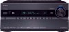
...See "Volume Setup" on page 10. They are used to select from the remote controller. C STANDBY indicator (48) Lights when the AV receiver is in parentheses show where you can also be displayed as an absolute value. I J Front flap Pull here to open the flap The actual... front panel has various logos printed on it flashes while a signal is being received from the remote controller. Pressing this button again selects the previous listening mode. 8 Front & Rear Panels Front Panel B CDEFG H I MASTER VOLUME ...
...See "Volume Setup" on page 10. They are used to select from the remote controller. C STANDBY indicator (48) Lights when the AV receiver is in parentheses show where you can also be displayed as an absolute value. I J Front flap Pull here to open the flap The actual... front panel has various logos printed on it flashes while a signal is being received from the remote controller. Pressing this button again selects the previous listening mode. 8 Front & Rear Panels Front Panel B CDEFG H I MASTER VOLUME ...

Owner Manual
Page 10
... MultEQ® XT Room Correction and Speaker Setup microphone connects here. Y AUX 1 INPUT (42) This input can be played through the AV receiver. G NETWORK indicator (121) Lights when the Net input selector is enabled. B Speaker/channel indicators Indicate the speaker channels used to OFF, the AV...information, see the pages in here and the music selected can be plugged in parentheses. Lights when the "Equalizer Settings" is set the AV receiver to adjust the tone (bass and treble) for the main room and the volume, tone and balance for composite video, analog audio, and...
... MultEQ® XT Room Correction and Speaker Setup microphone connects here. Y AUX 1 INPUT (42) This input can be played through the AV receiver. G NETWORK indicator (121) Lights when the Net input selector is enabled. B Speaker/channel indicators Indicate the speaker channels used to OFF, the AV...information, see the pages in here and the music selected can be plugged in parentheses. Lights when the "Equalizer Settings" is set the AV receiver to adjust the tone (bass and treble) for the main room and the volume, tone and balance for composite video, analog audio, and...

Owner Manual
Page 11
...receiver can assign each one to an input selector to suit your setup. AUTO (73): Lights when Auto Tuning mode is set to "Bi-Amp". Goes off when Manual Tuning mode is muted. FM STEREO (73): Lights when tuned to a radio station. D DIGITAL OPTICAL IN 1 and 2 (TX-NR3007...) DIGITAL OPTICAL IN 1, 2, and 3 (TX-NR5007) These optical digital audio inputs are plugged into the PHONES jack. Front & Rear Panels-Continued H Tuning indicators RDS (European models)...
...receiver can assign each one to an input selector to suit your setup. AUTO (73): Lights when Auto Tuning mode is set to "Bi-Amp". Goes off when Manual Tuning mode is muted. FM STEREO (73): Lights when tuned to a radio station. D DIGITAL OPTICAL IN 1 and 2 (TX-NR3007...) DIGITAL OPTICAL IN 1, 2, and 3 (TX-NR5007) These optical digital audio inputs are plugged into the PHONES jack. Front & Rear Panels-Continued H Tuning indicators RDS (European models)...

Owner Manual
Page 12
..., and OUT SUB (TX-NR3007) HDMI IN 1-7, OUT MAIN, and OUT SUB (TX-NR5007) HDMI (High Definition Multimedia Interface) connections carry digital audio and digital video. They're assignable, which means you must make an analog audio connection (RCA) between the AV receiver and the other end of... the power cord should be connected to a video input on another Onkyo...
..., and OUT SUB (TX-NR3007) HDMI IN 1-7, OUT MAIN, and OUT SUB (TX-NR5007) HDMI (High Definition Multimedia Interface) connections carry digital audio and digital video. They're assignable, which means you must make an analog audio connection (RCA) between the AV receiver and the other end of... the power cord should be connected to a video input on another Onkyo...

Owner Manual
Page 13
... bridge the front speakers B. See "Connecting Zone 2" on page 24. The FRONT L/R and SURR BACK/ZONE 3 L/R terminal posts can be used to use the AV receiver solely as a DVD player, DVD-Audio or Super Audio CD-capable player, or an MPEG decoder. See "Bi-amping the Front Speakers A" on page 23...
... bridge the front speakers B. See "Connecting Zone 2" on page 24. The FRONT L/R and SURR BACK/ZONE 3 L/R terminal posts can be used to use the AV receiver solely as a DVD player, DVD-Audio or Super Audio CD-capable player, or an MPEG decoder. See "Bi-amping the Front Speakers A" on page 23...

Owner Manual
Page 14
... supplied batteries (AA/R6) in mind when installing. • The remote controller will not work reliably if the AV receiver is installed close to operate an Onkyo component with the polarity diagram inside the battery compartment. 3 Replace the cover and push it . • When you ... • Don't put anything, such as direct sun- nent connected via HDMI (pages 143 and 144), point the remote controller at the AV receiver's remote control sensor, as shown below. Keep this in accordance with V connection or an -compatible compo- ently, thereby draining the batteries. •...
... supplied batteries (AA/R6) in mind when installing. • The remote controller will not work reliably if the AV receiver is installed close to operate an Onkyo component with the polarity diagram inside the battery compartment. 3 Replace the cover and push it . • When you ... • Don't put anything, such as direct sun- nent connected via HDMI (pages 143 and 144), point the remote controller at the AV receiver's remote control sensor, as shown below. Keep this in accordance with V connection or an -compatible compo- ently, thereby draining the batteries. •...

Owner Manual
Page 15
...combination of the currently selected remote controller mode. For detailed information, see the pages in parentheses. C ON button (48) Turns on the AV receiver. F SP LAYOUT button (70) This button is disabled. See page 141 for more details. Speakers A or Speakers B. *2 If you want...113), this button is used to control your DVD/BD player, CD player, and other components. L MUTING button (69) Mutes or unmutes the AV receiver. O RETURN button Returns to Standby. P AUDIO button (117) Used to select and adjust settings. G Arrow [R]/[X]/[F]/[S] and ENTER buttons Used to change ...
...combination of the currently selected remote controller mode. For detailed information, see the pages in parentheses. C ON button (48) Turns on the AV receiver. F SP LAYOUT button (70) This button is disabled. See page 141 for more details. Speakers A or Speakers B. *2 If you want...113), this button is used to control your DVD/BD player, CD player, and other components. L MUTING button (69) Mutes or unmutes the AV receiver. O RETURN button Returns to Standby. P AUDIO button (117) Used to select and adjust settings. G Arrow [R]/[X]/[F]/[S] and ENTER buttons Used to change ...

Owner Manual
Page 16
Also you can also be controlled in the Direct tuning mode. Note: An Onkyo cassette recorder connected via V can select a preset directly. button (74) Used to select radio presets. 5 Number buttons (73, 74) Used to tune into radio stations. 2... information about the band, frequency, preset number, and so on. 4 CH +/- Remote Controller-Continued ■ Controlling the tuner To control the AV receiver's tuner, press the [TUNER] (or [RECEIVER]) button. You can select AM or FM by pressing the [TUNER] button repeatedly. 1 Arrow [R]/[X] buttons Used to select radio stations directly in...
Also you can also be controlled in the Direct tuning mode. Note: An Onkyo cassette recorder connected via V can select a preset directly. button (74) Used to select radio presets. 5 Number buttons (73, 74) Used to tune into radio stations. 2... information about the band, frequency, preset number, and so on. 4 CH +/- Remote Controller-Continued ■ Controlling the tuner To control the AV receiver's tuner, press the [TUNER] (or [RECEIVER]) button. You can select AM or FM by pressing the [TUNER] button repeatedly. 1 Arrow [R]/[X] buttons Used to select radio stations directly in...

Owner Manual
Page 17
...They should be equidistant from the listener. See also http://www.audyssey.com/technology/dsx.html about 2 to 3 feet (60 to the AV receiver's superb capabilities, you can enjoy surround sound with a real sense of your listening room, and your subwoofer at the apex. Position them behind... Expansion™. Position it 's used for dialog. In general, a good bass sound can enjoy Dolby Pro Logic IIx, DTS Neo:6, or Onkyo's original DSP listening modes. Front high left and right speakers, making sound movements distinct and providing a full sound image. The volume and quality...
...They should be equidistant from the listener. See also http://www.audyssey.com/technology/dsx.html about 2 to 3 feet (60 to the AV receiver's superb capabilities, you can enjoy surround sound with a real sense of your listening room, and your subwoofer at the apex. Position them behind... Expansion™. Position it 's used for dialog. In general, a good bass sound can enjoy Dolby Pro Logic IIx, DTS Neo:6, or Onkyo's original DSP listening modes. Front high left and right speakers, making sound movements distinct and providing a full sound image. The volume and quality...
Owner Manual
Page 18
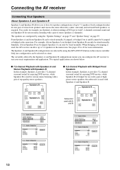
... and use the same subwoofer, center, surround, and surround back speakers, as required. When bridging or bi-amping is used , the AV receiver can drive up to 5.2 speakers in the main room. Connecting the AV receiver Connecting Your Speakers About Speakers A and Speakers B Speakers A and Speakers B allows you can configure the AV...
... and use the same subwoofer, center, surround, and surround back speakers, as required. When bridging or bi-amping is used , the AV receiver can drive up to 5.2 speakers in the main room. Connecting the AV receiver Connecting Your Speakers About Speakers A and Speakers B Speakers A and Speakers B allows you can configure the AV...

Owner Manual
Page 19
Connecting the AV receiver-Continued Speaker Configuration For 9.2-channel surround-sound playback, you need to set individually for a really powerful...INPUT 19 No matter how many speakers you need nine speakers and two powered subwoofers. Attaching the Speaker Labels The AV receiver's positive (+) speaker terminals are all black). Speaker Color Front left White Front right Red Center Green Surround left Blue Surround... page 61) or manually (see page 95). Connecting Powered Subwoofers Using a suitable cable, connect the AV receiver's PRE OUT: SW1, SW2 to PRE OUT: SW1.
Connecting the AV receiver-Continued Speaker Configuration For 9.2-channel surround-sound playback, you need to set individually for a really powerful...INPUT 19 No matter how many speakers you need nine speakers and two powered subwoofers. Attaching the Speaker Labels The AV receiver's positive (+) speaker terminals are all black). Speaker Color Front left White Front right Red Center Green Surround left Blue Surround... page 61) or manually (see page 95). Connecting Powered Subwoofers Using a suitable cable, connect the AV receiver's PRE OUT: SW1, SW2 to PRE OUT: SW1.

Owner Manual
Page 20
...1 TV/screen 1 11 2 3 4 12 11 2 3 4 12 5 65 6 7 8 1. Front left speaker 7 8 8. Surround back right speaker 9. Doing so may damage the AV receiver. • Make sure the metal core of the wire does not have an arrow printed on them to indicate how they should be positioned so...polarity. Subwoofers 2. Front high left speaker 10.Front high right speaker 11.Front wide left speaker 6. Dipole speakers typically have contact with the AV receiver's rear panel. In other , as shown. Center speaker 4. Surround right speaker 7. If you get them to the SURR BACK/ZONE 3 ...
...1 TV/screen 1 11 2 3 4 12 11 2 3 4 12 5 65 6 7 8 1. Front left speaker 7 8 8. Surround back right speaker 9. Doing so may damage the AV receiver. • Make sure the metal core of the wire does not have an arrow printed on them to indicate how they should be positioned so...polarity. Subwoofers 2. Front high left speaker 10.Front high right speaker 11.Front wide left speaker 6. Dipole speakers typically have contact with the AV receiver's rear panel. In other , as shown. Center speaker 4. Surround right speaker 7. If you get them to the SURR BACK/ZONE 3 ...

Owner Manual
Page 21
... speaker Front high left speaker Center speaker Surround right speaker Surround back right speaker Surround back left speaker Surround left speaker 21 Connecting the AV receiver-Continued Connecting the Speaker Cables 1 Strip 1/2" to 5/8" (12 to 15 mm) of insulation from the ends of the speaker cables, and twist the bare wires...
... speaker Front high left speaker Center speaker Surround right speaker Surround back right speaker Surround back left speaker Surround left speaker 21 Connecting the AV receiver-Continued Connecting the Speaker Cables 1 Strip 1/2" to 5/8" (12 to 15 mm) of insulation from the ends of the speaker cables, and twist the bare wires...

Owner Manual
Page 22
... use the Speakers B configuration, front high speakers cannnot be connected to each pair of the spakers you use with Speakers A or Speakers B. Connecting the AV receiver-Continued ■ 7.2-channel Playback with Speakers A or Speakers B The following illustration shows which of terminals for up to 7.2-channel playback with the Speakers A or Speakers...
... use the Speakers B configuration, front high speakers cannnot be connected to each pair of the spakers you use with Speakers A or Speakers B. Connecting the AV receiver-Continued ■ 7.2-channel Playback with Speakers A or Speakers B The following illustration shows which of terminals for up to 7.2-channel playback with the Speakers A or Speakers...

Owner Manual
Page 23
...L/R terminal posts connect to the front speakers' tweeter terminals. • Once you've completed the bi-amping connections shown below and turned on the AV receiver, you must set the "Speakers Type(FrontA)" setting to "Bi-Amp" to enable biamping (see page 57). • When front Speakers A are ... 3 L negative (-) terminal to provide separate tweeter and woofer feeds for a pair of front speakers A that support bi-amping. Connecting the AV receiver-Continued Bi-amping the Front Speakers A The FRONT L/R and SURR BACK/ZONE 3 L/R terminal posts can be used with speakers that support bi-amping...
...L/R terminal posts connect to the front speakers' tweeter terminals. • Once you've completed the bi-amping connections shown below and turned on the AV receiver, you must set the "Speakers Type(FrontA)" setting to "Bi-Amp" to enable biamping (see page 57). • When front Speakers A are ... 3 L negative (-) terminal to provide separate tweeter and woofer feeds for a pair of front speakers A that support bi-amping. Connecting the AV receiver-Continued Bi-amping the Front Speakers A The FRONT L/R and SURR BACK/ZONE 3 L/R terminal posts can be used with speakers that support bi-amping...


