
Owner Manual
Page 1
... Modes ........81 Advanced Setup 92 NET/USB 120 Multi Zone 130 Controlling Other Components....139 Others 154 En AV Receiver TX-NR3007 TX-NR5007 Instruction Manual Thank you to obtain optimum performance and listening enjoyment from your new AV Receiver. Following the instructions in the unit. Please read this manual thoroughly before making connections and plugging in...
... Modes ........81 Advanced Setup 92 NET/USB 120 Multi Zone 130 Controlling Other Components....139 Others 154 En AV Receiver TX-NR3007 TX-NR5007 Instruction Manual Thank you to obtain optimum performance and listening enjoyment from your new AV Receiver. Following the instructions in the unit. Please read this manual thoroughly before making connections and plugging in...
Owner Manual
Page 4
... brown must be connected to the terminal which is not supplied for your AC outlet does not match with the plug on the AV receiver's power cord (adapter varies from country to country). *How to BS1362 and have the following code: Blue: Neutral Brown: Live... EN60065, EN55013, EN55020 and EN61000-3-2, -3-3. Fit a suitable fuse in accordance with an appropriate fuse. For European Models Declaration of Conformity We, ONKYO EUROPE ELECTRONICS GmbH LIEGNITZERSTRASSE 6, 82194 GROEBENZELL, GERMANY declare in own responsibility, that indicated on packaging, the letter at the end of color. 4...
... brown must be connected to the terminal which is not supplied for your AC outlet does not match with the plug on the AV receiver's power cord (adapter varies from country to country). *How to BS1362 and have the following code: Blue: Neutral Brown: Live... EN60065, EN55013, EN55020 and EN61000-3-2, -3-3. Fit a suitable fuse in accordance with an appropriate fuse. For European Models Declaration of Conformity We, ONKYO EUROPE ELECTRONICS GmbH LIEGNITZERSTRASSE 6, 82194 GROEBENZELL, GERMANY declare in own responsibility, that indicated on packaging, the letter at the end of color. 4...

Owner Manual
Page 5
...139 Preprogrammed Remote Control Codes 139 Looking up for Remote Control Code 139 Entering Remote Control Codes 141 Remote Control Codes for Onkyo Components Connected via V 142 Resetting REMOTE MODE Buttons 142 Resetting the Remote Controller 142 Controlling a TV 143 Controlling a ... Recorder 149 Activities Setup 150 Learning Commands 152 Using Normal Macros 153 Others Troubleshooting 154 Specifications (TX-NR3007 160 Specifications (TX-NR5007 161 Video Resolution Chart 162 * To reset the AV receiver to its factory defaults, turn it on and, while holding down the [VCR/DVR] button...
...139 Preprogrammed Remote Control Codes 139 Looking up for Remote Control Code 139 Entering Remote Control Codes 141 Remote Control Codes for Onkyo Components Connected via V 142 Resetting REMOTE MODE Buttons 142 Resetting the Remote Controller 142 Controlling a TV 143 Controlling a ... Recorder 149 Activities Setup 150 Learning Commands 152 Using Normal Macros 153 Others Troubleshooting 154 Specifications (TX-NR3007 160 Specifications (TX-NR5007 161 Video Resolution Chart 162 * To reset the AV receiver to its factory defaults, turn it on and, while holding down the [VCR/DVR] button...

Owner Manual
Page 8
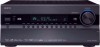
.... The transmitter transmits setting data to -2 dB, -81.5 dB through +18.0 dB (relative display). C STANDBY indicator (48) Lights when the AV receiver is in parentheses show where you can also be displayed as an absolute value. The page numbers in Standby mode, and it . J PURE AUDIO... Front & Rear Panels Front Panel B CDEFG H I MASTER VOLUME control (67) and indicator This control is used to adjust the volume of the AV receiver to the remote controller. B ON/STANDBY button (48) This button is selected. F Input selector buttons (67) These buttons are not shown here ...
.... The transmitter transmits setting data to -2 dB, -81.5 dB through +18.0 dB (relative display). C STANDBY indicator (48) Lights when the AV receiver is in parentheses show where you can also be displayed as an absolute value. The page numbers in Standby mode, and it . J PURE AUDIO... Front & Rear Panels Front Panel B CDEFG H I MASTER VOLUME control (67) and indicator This control is used to adjust the volume of the AV receiver to the remote controller. B ON/STANDBY button (48) This button is selected. F Input selector buttons (67) These buttons are not shown here ...

Owner Manual
Page 10
...-Continued W SETUP MIC jack (62) Audyssey MultEQ® XT Room Correction and Speaker Setup microphone connects here. When set is set the AV receiver to adjust the tone (bass and treble) for the main room and the volume, tone and balance for composite video, analog audio, and... optical digital audio. Vol (101, 118): Lights when "Dolby Volume" is enabled. The following abbreviations indicate which speaker set to OFF, the AV receiver is used to connect a camcorder, game console, and so on. AUX 1 INPUT HDMI (31) Used to "Audyssey" or Audyssey Dynamic Surround Expansion...
...-Continued W SETUP MIC jack (62) Audyssey MultEQ® XT Room Correction and Speaker Setup microphone connects here. When set is set the AV receiver to adjust the tone (bass and treble) for the main room and the volume, tone and balance for composite video, analog audio, and... optical digital audio. Vol (101, 118): Lights when "Dolby Volume" is enabled. The following abbreviations indicate which speaker set to OFF, the AV receiver is used to connect a camcorder, game console, and so on. AUX 1 INPUT HDMI (31) Used to "Audyssey" or Audyssey Dynamic Surround Expansion...

Owner Manual
Page 11
...for example, installed in a cabinet. They're assignable, which means you can be connected to the IR IN jack, allowing you to control the AV receiver while you're in Zone 2/3, or control it when it's out of audio input that supports RDS (Radio Data System). K BTL indicator (...is set . C IR IN/OUT A commercially available IR receiver can be connected to the IR OUT jack to pass IR (infrared) remote control signals through to other components. D DIGITAL OPTICAL IN 1 and 2 (TX-NR3007) DIGITAL OPTICAL IN 1, 2, and 3 (TX-NR5007) These optical digital audio inputs are plugged into the...
...for example, installed in a cabinet. They're assignable, which means you can be connected to the IR IN jack, allowing you to control the AV receiver while you're in Zone 2/3, or control it when it's out of audio input that supports RDS (Radio Data System). K BTL indicator (...is set . C IR IN/OUT A commercially available IR receiver can be connected to the IR OUT jack to pass IR (infrared) remote control signals through to other components. D DIGITAL OPTICAL IN 1 and 2 (TX-NR3007) DIGITAL OPTICAL IN 1, 2, and 3 (TX-NR5007) These optical digital audio inputs are plugged into the...

Owner Manual
Page 12
...a 12-volt trigger signal is for connecting an FM antenna. J HDMI IN 1-6, OUT MAIN, and OUT SUB (TX-NR3007) HDMI IN 1-7, OUT MAIN, and OUT SUB (TX-NR5007) HDMI (High Definition Multimedia Interface) connections carry digital audio and digital video. P AC INLET The supplied power ...music selected can be played through the AV receiver. M COMPONENT VIDEO MONITOR OUT These RCA component video outputs are for connecting a turntable. The AV receiver's remote controller can then be used to the 12-volt trigger input on another Onkyo AV component. The HDMI outputs are for control...
...a 12-volt trigger signal is for connecting an FM antenna. J HDMI IN 1-6, OUT MAIN, and OUT SUB (TX-NR3007) HDMI IN 1-7, OUT MAIN, and OUT SUB (TX-NR5007) HDMI (High Definition Multimedia Interface) connections carry digital audio and digital video. P AC INLET The supplied power ...music selected can be played through the AV receiver. M COMPONENT VIDEO MONITOR OUT These RCA component video outputs are for connecting a turntable. The AV receiver's remote controller can then be used to the 12-volt trigger input on another Onkyo AV component. The HDMI outputs are for control...

Owner Manual
Page 13
... BACK L/R, and FRONT HIGH/WIDE L/R These multichannel analog audio outputs can be connected to connect the speakers in Zone 3. See pages 18 to use the AV receiver solely as a DVD player, DVD-Audio or Super Audio CD-capable player, or an MPEG decoder. You can connect the powered subwoofer with surround speakers...
... BACK L/R, and FRONT HIGH/WIDE L/R These multichannel analog audio outputs can be connected to connect the speakers in Zone 3. See pages 18 to use the AV receiver solely as a DVD player, DVD-Audio or Super Audio CD-capable player, or an MPEG decoder. You can connect the powered subwoofer with surround speakers...

Owner Manual
Page 14
...When you want to operate an Onkyo component with the polarity diagram inside the battery compartment. 3 Replace the cover and push it and the AV receiver's remote con- ler may not work reliably if the AV receiver is installed in the same room, or the AV receiver is installed close to bright light..., because the buttons may not work reliably if the AV receiver is used in a rack behind colored glass doors. trol sensor. • When the remote control codes have been registered and you want to operate an Onkyo component without V connection, point the remote controller at the...
...When you want to operate an Onkyo component with the polarity diagram inside the battery compartment. 3 Replace the cover and push it and the AV receiver's remote con- ler may not work reliably if the AV receiver is installed in the same room, or the AV receiver is installed close to bright light..., because the buttons may not work reliably if the AV receiver is used in a rack behind colored glass doors. trol sensor. • When the remote control codes have been registered and you want to operate an Onkyo component without V connection, point the remote controller at the...

Owner Manual
Page 15
... eight seconds, press the REMOTE MODE button. F SP LAYOUT button (70) This button is disabled. L MUTING button (69) Mutes or unmutes the AV receiver. P AUDIO button (117) Used to 149) Selects the remote controller modes and the input sources. N VIDEO button (49, 53, 105) Used ...to Standby. B STANDBY button (48) Sets the AV receiver to change audio settings. M VOL [R]/[X] button (67) Adjusts the volume of the AV receiver regardless of surround back and front high, or surround back and front wide speakers. G Arrow [R]/[X]/[F]/[S] and ...
... eight seconds, press the REMOTE MODE button. F SP LAYOUT button (70) This button is disabled. L MUTING button (69) Mutes or unmutes the AV receiver. P AUDIO button (117) Used to 149) Selects the remote controller modes and the input sources. N VIDEO button (49, 53, 105) Used ...to Standby. B STANDBY button (48) Sets the AV receiver to change audio settings. M VOL [R]/[X] button (67) Adjusts the volume of the AV receiver regardless of surround back and front high, or surround back and front wide speakers. G Arrow [R]/[X]/[F]/[S] and ...

Owner Manual
Page 16
... band, frequency, preset number, and so on. 4 CH +/- Remote Controller-Continued ■ Controlling the tuner To control the AV receiver's tuner, press the [TUNER] (or [RECEIVER]) button. You can select AM or FM by pressing the [TUNER] button repeatedly. 1 Arrow [R]/[X] buttons Used to select radio... stations directly in Receiver mode (see page 149). 16 Note: An Onkyo cassette recorder connected via V can select a preset directly. ...
... band, frequency, preset number, and so on. 4 CH +/- Remote Controller-Continued ■ Controlling the tuner To control the AV receiver's tuner, press the [TUNER] (or [RECEIVER]) button. You can select AM or FM by pressing the [TUNER] button repeatedly. 1 Arrow [R]/[X] buttons Used to select radio... stations directly in Receiver mode (see page 149). 16 Note: An Onkyo cassette recorder connected via V can select a preset directly. ...

Owner Manual
Page 17
... inward so as shown. They significantly enhance the spatial experience. With DVDs you can enjoy Dolby Pro Logic IIx, DTS Neo:6, or Onkyo's original DSP listening modes. Front high left and right speakers These speakers are necessary to enjoy Dolby Pro Logic IIz Height, and Audyssey...to 3 feet (60 to 100 cm) above ear level. Angle them at the apex. About Home Theater Enjoying Home Theater Thanks to the AV receiver's superb capabilities, you can also enjoy THX Surround EX (THX-certified THX speaker system recommended). They enhance the realism of the LFE (Low-...
... inward so as shown. They significantly enhance the spatial experience. With DVDs you can enjoy Dolby Pro Logic IIx, DTS Neo:6, or Onkyo's original DSP listening modes. Front high left and right speakers These speakers are necessary to enjoy Dolby Pro Logic IIz Height, and Audyssey...to 3 feet (60 to 100 cm) above ear level. Angle them at the apex. About Home Theater Enjoying Home Theater Thanks to the AV receiver's superb capabilities, you can also enjoy THX Surround EX (THX-certified THX speaker system recommended). They enhance the realism of the LFE (Low-...
Owner Manual
Page 18
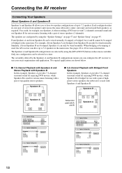
...Type(FrontA) Speakers Type(FrontB) Powered Zone2 Powered Zone3 6ohms Normal Normal Not Act Not Act 2-2. Only one configuration can configure the AV receiver to 7.2 speakers. See pages 22 to 5.2 speakers in the main room. You could, for serious music listening with Speakers A... offered by the Speakers A and Speakers B configurations means you to have two speaker configurations of top-quality stereo speakers. Connecting the AV receiver Connecting Your Speakers About Speakers A and Speakers B Speakers A and Speakers B allows you can be selected at the same time. SW1...
...Type(FrontA) Speakers Type(FrontB) Powered Zone2 Powered Zone3 6ohms Normal Normal Not Act Not Act 2-2. Only one configuration can configure the AV receiver to 7.2 speakers. See pages 22 to 5.2 speakers in the main room. You could, for serious music listening with Speakers A... offered by the Speakers A and Speakers B configurations means you to have two speaker configurations of top-quality stereo speakers. Connecting the AV receiver Connecting Your Speakers About Speakers A and Speakers B Speakers A and Speakers B allows you can be selected at the same time. SW1...

Owner Manual
Page 19
...and you're using an external amplifier, connect the PRE OUT: SW1, SW2 to an input on the amp. Attaching the Speaker Labels The AV receiver's positive (+) speaker terminals are all red (the negative (-) speaker terminals are recommended for each output. To get the best from your surround ...speaker code directly into the center hole of speakers that you have. Then all black). Connecting Powered Subwoofers Using a suitable cable, connect the AV receiver's PRE OUT: SW1, SW2 to an input on the number of the speaker terminal. If your powered subwoofer, as shown. Powered subwoofer LINE...
...and you're using an external amplifier, connect the PRE OUT: SW1, SW2 to an input on the amp. Attaching the Speaker Labels The AV receiver's positive (+) speaker terminals are all red (the negative (-) speaker terminals are recommended for each output. To get the best from your surround ...speaker code directly into the center hole of speakers that you have. Then all black). Connecting Powered Subwoofers Using a suitable cable, connect the AV receiver's PRE OUT: SW1, SW2 to an input on the number of the speaker terminal. If your powered subwoofer, as shown. Powered subwoofer LINE...

Owner Manual
Page 20
... and should be positioned so that their arrows point toward each of the two surround speakers to the SURR L/R terminals. Doing so may damage the AV receiver. • Don't connect one cable to each speaker terminal. Dipole speakers Normal speakers 9 10 9 10 1 TV/screen 1 1 TV/screen 1 11 2 3 ...speakers for a long period of time, the built-in two directions. Subwoofers 2. Surround back right speaker 9. Connecting the AV receiver-Continued Using Dipole Speakers You can connect speakers with your speakers. • Pay close attention to speaker wiring polarity. Surround...
... and should be positioned so that their arrows point toward each of the two surround speakers to the SURR L/R terminals. Doing so may damage the AV receiver. • Don't connect one cable to each speaker terminal. Dipole speakers Normal speakers 9 10 9 10 1 TV/screen 1 1 TV/screen 1 11 2 3 ...speakers for a long period of time, the built-in two directions. Subwoofers 2. Surround back right speaker 9. Connecting the AV receiver-Continued Using Dipole Speakers You can connect speakers with your speakers. • Pay close attention to speaker wiring polarity. Surround...

Owner Manual
Page 21
... left speaker Front high left speaker Center speaker Surround right speaker Surround back right speaker Surround back left speaker Surround left speaker 21 Connecting the AV receiver-Continued Connecting the Speaker Cables 1 Strip 1/2" to 5/8" (12 to 15 mm) of insulation from the ends of the speaker cables, and twist the bare wires...
... left speaker Front high left speaker Center speaker Surround right speaker Surround back right speaker Surround back left speaker Surround left speaker 21 Connecting the AV receiver-Continued Connecting the Speaker Cables 1 Strip 1/2" to 5/8" (12 to 15 mm) of insulation from the ends of the speaker cables, and twist the bare wires...

Owner Manual
Page 22
... FRONT WIDE/ZONE 2 R. • The speakers are configured by using only one surround back speaker, connect it to the SURR BACK/ZONE 3 L terminal. Connecting the AV receiver-Continued ■ 7.2-channel Playback with Speakers A or Speakers B The following illustration shows which of terminals for up to FRONT R.
... FRONT WIDE/ZONE 2 R. • The speakers are configured by using only one surround back speaker, connect it to the SURR BACK/ZONE 3 L terminal. Connecting the AV receiver-Continued ■ 7.2-channel Playback with Speakers A or Speakers B The following illustration shows which of terminals for up to FRONT R.

Owner Manual
Page 23
...terminal posts connect to the front speakers' tweeter terminals. • Once you've completed the bi-amping connections shown below and turned on the AV receiver, you must be wired normally or not used. Tweeter (high) Tweeter (high) Woofer (low) Right speaker Woofer (low) Left speaker 23...and woofer (low) terminals. • Bi-amping can only be used. • For bi-amping, the FRONT L/R terminal posts con- Connecting the AV receiver-Continued Bi-amping the Front Speakers A The FRONT L/R and SURR BACK/ZONE 3 L/R terminal posts can be used with speakers that support bi-amping. ...
...terminal posts connect to the front speakers' tweeter terminals. • Once you've completed the bi-amping connections shown below and turned on the AV receiver, you must be wired normally or not used. Tweeter (high) Tweeter (high) Woofer (low) Right speaker Woofer (low) Left speaker 23...and woofer (low) terminals. • Bi-amping can only be used. • For bi-amping, the FRONT L/R terminal posts con- Connecting the AV receiver-Continued Bi-amping the Front Speakers A The FRONT L/R and SURR BACK/ZONE 3 L/R terminal posts can be used with speakers that support bi-amping. ...

Owner Manual
Page 24
...almost double the output power for bridging. And connect the AV receiver's SURR BACK/ZONE 3 R positive (+) terminal to the right speaker's negative (-) terminal. 2 Connect the AV receiver's FRONT L positive (+) terminal to do so may seriously damage the AV receiver. • When using bridging, make sure that your... FRONT L/R and SURR BACK/ZONE 3 L/R terminals are not. • Once you've completed the bridging connections shown below and turned on the AV receiver, you must set the "Speakers Type(FrontA)" setting to "BTL" to enable bridging (see page 57). • When front Speakers A are ...
...almost double the output power for bridging. And connect the AV receiver's SURR BACK/ZONE 3 R positive (+) terminal to the right speaker's negative (-) terminal. 2 Connect the AV receiver's FRONT L positive (+) terminal to do so may seriously damage the AV receiver. • When using bridging, make sure that your... FRONT L/R and SURR BACK/ZONE 3 L/R terminals are not. • Once you've completed the bridging connections shown below and turned on the AV receiver, you must set the "Speakers Type(FrontA)" setting to "BTL" to enable bridging (see page 57). • When front Speakers A are ...

Owner Manual
Page 25
...speakers' tweeter terminals. • Once you've completed the bi-amping connections shown below and turned on the AV receiver, you must be wired normally. Connecting the AV receiver-Continued Bi-amping the Front Speakers B The FRONT WIDE/ZONE 2 L/R and SURR BACK/ZONE 3 L/R ...be used . • For bi-amping, the FRONT WIDE/ZONE 2 L/R ter- And connect the AV receiver's FRONT WIDE/ZONE 2 R negative (-) terminal to the right speaker's negative (-) Woofer (low) terminal. 2 Connect the AV receiver's SURR BACK/ZONE 3 R positive (+) terminal to the right speaker's positive (+) Woofer (low) ...
...speakers' tweeter terminals. • Once you've completed the bi-amping connections shown below and turned on the AV receiver, you must be wired normally. Connecting the AV receiver-Continued Bi-amping the Front Speakers B The FRONT WIDE/ZONE 2 L/R and SURR BACK/ZONE 3 L/R ...be used . • For bi-amping, the FRONT WIDE/ZONE 2 L/R ter- And connect the AV receiver's FRONT WIDE/ZONE 2 R negative (-) terminal to the right speaker's negative (-) Woofer (low) terminal. 2 Connect the AV receiver's SURR BACK/ZONE 3 R positive (+) terminal to the right speaker's positive (+) Woofer (low) ...


