
Operating Instructions
Page 5
...produce lower screen definition, however, compared to write on , the power indicator will use the special pen or other object can be used to input characters and lines on the screen. NOTE: When the power switch is initializing its internal settings. while the indicator is flashing, do not ... turned on the screen. Using the special pen allows the drawing of unit Mode selector switch Set the mode switch in accordance with the dedicated input pen. NORMAL Mode: In this list, confirm that all accessories are present, and check them off one-by-one here ✔ . ACCESSORIES...
...produce lower screen definition, however, compared to write on , the power indicator will use the special pen or other object can be used to input characters and lines on the screen. NOTE: When the power switch is initializing its internal settings. while the indicator is flashing, do not ... turned on the screen. Using the special pen allows the drawing of unit Mode selector switch Set the mode switch in accordance with the dedicated input pen. NORMAL Mode: In this list, confirm that all accessories are present, and check them off one-by-one here ✔ . ACCESSORIES...

Operating Instructions
Page 10
When the pop-up menu appears, leftclick on your computer configuration. 23 En mechanical pencils or other object in the task tray. NOTE: Input to the special dedicated pen; NOTE: The actual appearance of your mouse, left-click on the CBdrvU icon in addition to the unit can be ...
When the pop-up menu appears, leftclick on your computer configuration. 23 En mechanical pencils or other object in the task tray. NOTE: Input to the special dedicated pen; NOTE: The actual appearance of your mouse, left-click on the CBdrvU icon in addition to the unit can be ...

Operating Instructions
Page 12
... closely together, set to PEN. red signal filter, blocking signal. are operated closely together in power-saving appropriate. Cannot input with capability of mes- No response to input or can't write in power sav- ÷ Main unit will not operate when ÷ Change power-saving mode as...of supplying 500mA from outlet. Computer remains in some places. ÷ User touched screen during boot ÷ Disconnect USB connector and process (during input by two different people. The device is loose or has been ÷ Connect USB cable securely. CAUTION: ÷ If two or more ...
... closely together, set to PEN. red signal filter, blocking signal. are operated closely together in power-saving appropriate. Cannot input with capability of mes- No response to input or can't write in power sav- ÷ Main unit will not operate when ÷ Change power-saving mode as...of supplying 500mA from outlet. Computer remains in some places. ÷ User touched screen during boot ÷ Disconnect USB connector and process (during input by two different people. The device is loose or has been ÷ Connect USB cable securely. CAUTION: ÷ If two or more ...

Technical Manual
Page 2
... USE THE STANDARD MOUNTING COMPONENTS 4.1 Standard Mounting Components Features and Characteristics 50 4.2 Handling the Standard Mounting Components 51 4.2.1 Handling precautions 51 4.2.2...Installing the mounting hardware and mounting the plasma display ...... 76 4.8.4 Assembly procedure 77 4.8.5 Angle setup 78 4.9 Tiltable Plasma Display Wall-Mount Hardware: PDK-5013 80...PDP-503CMX or PDP-503MXE 94 BEFORE BEGINNING ADJUSTMENTS 5.1 Before Beginning Adjustments 96 5.1.1 Operating mode 96 5.1.2 Combination use of remote control unit, operating panel and PC 97 5.1.3 Lists of supported input...
... USE THE STANDARD MOUNTING COMPONENTS 4.1 Standard Mounting Components Features and Characteristics 50 4.2 Handling the Standard Mounting Components 51 4.2.1 Handling precautions 51 4.2.2...Installing the mounting hardware and mounting the plasma display ...... 76 4.8.4 Assembly procedure 77 4.8.5 Angle setup 78 4.9 Tiltable Plasma Display Wall-Mount Hardware: PDK-5013 80...PDP-503CMX or PDP-503MXE 94 BEFORE BEGINNING ADJUSTMENTS 5.1 Before Beginning Adjustments 96 5.1.1 Operating mode 96 5.1.2 Combination use of remote control unit, operating panel and PC 97 5.1.3 Lists of supported input...
Technical Manual
Page 3
... 133 4) Setting the 4-screen display (2x2 mode) ... 134 5) Setting brightness enhancement at screen center 135 6) Setting the HDTV MODE 136 7) Setting component input 137 8) Adjusting SUB VOLUME 138 9) Setting the OSD display 140 10) Setting the baud rate 141 11) Setting OFF TIMER 142 12) Setting FULL MASK... 149 19) Setting the cooling fan control formula ..... 150 20) Assigning a name to the monitor 151 21) Assigning an ID 152 22) Input settings when using a video card other than the PDA-5002 153 23) Simple checking of internal temperature .. 154 24) Checking the accumulated ON time...
... 133 4) Setting the 4-screen display (2x2 mode) ... 134 5) Setting brightness enhancement at screen center 135 6) Setting the HDTV MODE 136 7) Setting component input 137 8) Adjusting SUB VOLUME 138 9) Setting the OSD display 140 10) Setting the baud rate 141 11) Setting OFF TIMER 142 12) Setting FULL MASK... 149 19) Setting the cooling fan control formula ..... 150 20) Assigning a name to the monitor 151 21) Assigning an ID 152 22) Input settings when using a video card other than the PDA-5002 153 23) Simple checking of internal temperature .. 154 24) Checking the accumulated ON time...

Technical Manual
Page 4
... PAD-5002 is installed are premised on the PDP-503CMX/PDP503MXE being equipped with a star "#". Input terminals INPUT 1,2 Input • Component video signal • RGB signals from AV devices other than PCs INPUT 3 Input Input S terminal (mini DIN 4 PIN connector) • Y/C separate video signal Pin jacks x 2 • Audio L/R signal INPUT 4 INPUT 5 Input Output Input Input BNC terminal • Composite video signal BNC terminal...
... PAD-5002 is installed are premised on the PDP-503CMX/PDP503MXE being equipped with a star "#". Input terminals INPUT 1,2 Input • Component video signal • RGB signals from AV devices other than PCs INPUT 3 Input Input S terminal (mini DIN 4 PIN connector) • Y/C separate video signal Pin jacks x 2 • Audio L/R signal INPUT 4 INPUT 5 Input Output Input Input BNC terminal • Composite video signal BNC terminal...

Technical Manual
Page 5
... (VGA) to 1024x768 (XGA) and 1280x768; Further, use . Free Installation Configuration Broader installation possibilities with color-bar signal input). 5 The thinner, lighter design, coupled to a minimum, producing clear, high-contrast images even in -house comparison of ... size differ depending on the input signal. Features Features and Functions of the PDP-503CMX/PDP-503MXE Plasma Display Introduces newly developed 50" XGA Wide Plasma Panel The new high-precision XGA 50" wide plasma panel pushes the envelope of previous high-luminance panels, producing brighter, clearer images with...
... (VGA) to 1024x768 (XGA) and 1280x768; Further, use . Free Installation Configuration Broader installation possibilities with color-bar signal input). 5 The thinner, lighter design, coupled to a minimum, producing clear, high-contrast images even in -house comparison of ... size differ depending on the input signal. Features Features and Functions of the PDP-503CMX/PDP-503MXE Plasma Display Introduces newly developed 50" XGA Wide Plasma Panel The new high-precision XGA 50" wide plasma panel pushes the envelope of previous high-luminance panels, producing brighter, clearer images with...
Technical Manual
Page 6
... card 1 Remote control unit holder 1 Display stand 2 Washer 2 Hexagon socket head screw (M8 x 40 2 CD-ROM (information files 1 Label for INPUT 4) Input Pin jack (x2) L/R ... 500mVrms/more than 10 kΩ Control-related RS-232C terminal: D-sub, 9-pin (male) (NOTE 1) Combination In/Out...× 714 (H) × 98 (D) mm 47-31/32 (W) × 28-1/8 (H) × 3-7/8 (D) in. Specifications 2.1 Specifications Light-emitting panel 50-inch plasma display panel Aspect ratio 16 : 9 PEL 1280 × 768 PEL pitch 0.858 (H•RGB trio) × 0.808 (V) mm Viewing angle Horizontal: more ...
... card 1 Remote control unit holder 1 Display stand 2 Washer 2 Hexagon socket head screw (M8 x 40 2 CD-ROM (information files 1 Label for INPUT 4) Input Pin jack (x2) L/R ... 500mVrms/more than 10 kΩ Control-related RS-232C terminal: D-sub, 9-pin (male) (NOTE 1) Combination In/Out...× 714 (H) × 98 (D) mm 47-31/32 (W) × 28-1/8 (H) × 3-7/8 (D) in. Specifications 2.1 Specifications Light-emitting panel 50-inch plasma display panel Aspect ratio 16 : 9 PEL 1280 × 768 PEL pitch 0.858 (H•RGB trio) × 0.808 (V) mm Viewing angle Horizontal: more ...

Technical Manual
Page 7
... (1600 x 1024) 7 Specifications (NOTE 1) (NOTE 2) (NOTE 3) The display is preset at the factory to Installation Site Requirements.) INPUT Response Signals INPUT 1, 2 & Video signals supported # Vertical Horizontal Frequency Frequency Fv (Hz) Fh (kHz) 15.625 50 28.1 31.25 15.734 31.5 60 33.75 45.0 67.5 Signal Format Component RGB Component RGB Component...
... (1600 x 1024) 7 Specifications (NOTE 1) (NOTE 2) (NOTE 3) The display is preset at the factory to Installation Site Requirements.) INPUT Response Signals INPUT 1, 2 & Video signals supported # Vertical Horizontal Frequency Frequency Fv (Hz) Fh (kHz) 15.625 50 28.1 31.25 15.734 31.5 60 33.75 45.0 67.5 Signal Format Component RGB Component RGB Component...

Technical Manual
Page 10
External Dimensions ø15.2 22.5 14 105 STANDBY/ON INPUT MENU ADJUST SET SCREEN SIZE AUTO SET UP 85.5 39 10
External Dimensions ø15.2 22.5 14 105 STANDBY/ON INPUT MENU ADJUST SET SCREEN SIZE AUTO SET UP 85.5 39 10

Technical Manual
Page 11
...of cursor buttons within operations is operating. Note When optional speakers have been connected, the operation panel on the unit. AUTO SET UP button When entering a computer signal to INPUT 1 or 2, automatically sets the POSITION and CLOCK/ PHASE to adjust various settings on the ...is in operation or standby mode. 5 KEY LOCK/UNLOCK Button (concealed button) This switches between main unit panel and remote control operation permitted/forbidden. 6 INPUT button Press to select input. 7 MENU button Press to open and close the on-screen menu. 8 ADJUST (5/∞/3/2) buttons Use to...
...of cursor buttons within operations is operating. Note When optional speakers have been connected, the operation panel on the unit. AUTO SET UP button When entering a computer signal to INPUT 1 or 2, automatically sets the POSITION and CLOCK/ PHASE to adjust various settings on the ...is in operation or standby mode. 5 KEY LOCK/UNLOCK Button (concealed button) This switches between main unit panel and remote control operation permitted/forbidden. 6 INPUT button Press to select input. 7 MENU button Press to open and close the on-screen menu. 8 ADJUST (5/∞/3/2) buttons Use to...
Technical Manual
Page 12
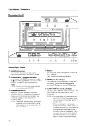
...OUTPUT (ANALOG RGB) G B INPUT2 (H/V SYNC) R HD VD 7Ω5Ô2k.Ω2 AUDIO INPUT OUTPUT (INPUT1/2) 56 7 89 0 Plasma Display Section 1 SPEAKER (R) terminal For connection of PIONEER components that have RGB or component# output jacks such as a personal computer, DVD player, or external... connector when the main power of this display is off . 12 4 RS-232C This terminal is initially input to an external monitor or other multi-projection. Controls and Connectors Connection Panel AC INLET OFF ON - = INPUT5 DIGITAL RGB AUDIO R INPUT3 S-VIDEO L AUDIO R INPUT4 VIDEO L...
...OUTPUT (ANALOG RGB) G B INPUT2 (H/V SYNC) R HD VD 7Ω5Ô2k.Ω2 AUDIO INPUT OUTPUT (INPUT1/2) 56 7 89 0 Plasma Display Section 1 SPEAKER (R) terminal For connection of PIONEER components that have RGB or component# output jacks such as a personal computer, DVD player, or external... connector when the main power of this display is off . 12 4 RS-232C This terminal is initially input to an external monitor or other multi-projection. Controls and Connectors Connection Panel AC INLET OFF ON - = INPUT5 DIGITAL RGB AUDIO R INPUT3 S-VIDEO L AUDIO R INPUT4 VIDEO L...

Technical Manual
Page 13
...jack to the audio output connector of the device connected to the plasma display's INPUT1 or INPUT2, or to the audio output connector ...to an AV amplifier or similar component. - Note: The left audio channel (L) jack is not compatible with monaural input sources. % INPUT4 (BNC jack) For connection of components that have a composite video output jack such as a ...AUDIO INPUT4 (RCA Pin jacks) Use to obtain sound when INPUT1, INPUT2 or INPUT5# is furnished with monaural input sources. # INPUT3 (S-video jack) For connection of the connected component's synchronization signal. Note: The left ...
...jack to the audio output connector of the device connected to the plasma display's INPUT1 or INPUT2, or to the audio output connector ...to an AV amplifier or similar component. - Note: The left audio channel (L) jack is not compatible with monaural input sources. % INPUT4 (BNC jack) For connection of components that have a composite video output jack such as a ...AUDIO INPUT4 (RCA Pin jacks) Use to obtain sound when INPUT1, INPUT2 or INPUT5# is furnished with monaural input sources. # INPUT3 (S-video jack) For connection of the connected component's synchronization signal. Note: The left ...

Technical Manual
Page 14
... 8 NC (No connection) 9 T.M.D.S. Data0/5 Shield 20 NC (No connection) 21 NC (No connection) 22 T.M.D.S. Controls and Connectors 2.4 Pin layout INPUT 1 (Mini D-sub, 15-pin connector; female) pin layout 1 2 Pin No. 9 17 24 16 Signal Assignment 1 T.M.D.S. Data2+ 3 T.M.D.S. ... connector; Data1+ 11 T.M.D.S. Combination IN 1 GND 2 NC (not connected) 3 TxD (output) 4 NC (not connected) 5 RxD (input) 6 NC (not connected) Combination OUT GND NC (not connected) RxD (input) NC (not connected) TxD (output) NC (not connected) 14 6 9 Pin No. 1 2 3 4 5 6 7 8 9...
... 8 NC (No connection) 9 T.M.D.S. Data0/5 Shield 20 NC (No connection) 21 NC (No connection) 22 T.M.D.S. Controls and Connectors 2.4 Pin layout INPUT 1 (Mini D-sub, 15-pin connector; female) pin layout 1 2 Pin No. 9 17 24 16 Signal Assignment 1 T.M.D.S. Data2+ 3 T.M.D.S. ... connector; Data1+ 11 T.M.D.S. Combination IN 1 GND 2 NC (not connected) 3 TxD (output) 4 NC (not connected) 5 RxD (input) 6 NC (not connected) Combination OUT GND NC (not connected) RxD (input) NC (not connected) TxD (output) NC (not connected) 14 6 9 Pin No. 1 2 3 4 5 6 7 8 9...

Technical Manual
Page 15
...screens and to adjust various settings on the unit. 6 MUTING button Press to mute the volume. 7 AUTO SET UP button When entering a computer signal to INPUT 1 or 2, automatically sets the POSITION and CLOCK/ PHASE to optimum values. 8 STANDBY/ON button Press to put the unit in operation or standby mode. 9... DISPLAY button Press to view the unit's current input and setup mode. 0 POINT ZOOM button Use to select and enlarge one part of cursor buttons within operations is clearly indicated at the bottom the...
...screens and to adjust various settings on the unit. 6 MUTING button Press to mute the volume. 7 AUTO SET UP button When entering a computer signal to INPUT 1 or 2, automatically sets the POSITION and CLOCK/ PHASE to optimum values. 8 STANDBY/ON button Press to put the unit in operation or standby mode. 9... DISPLAY button Press to view the unit's current input and setup mode. 0 POINT ZOOM button Use to select and enlarge one part of cursor buttons within operations is clearly indicated at the bottom the...

