Owner's Manual
Page 4
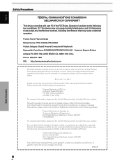
...or if you wish to purchase replacement parts, operating instructions, service manuals, or accessories, please call the number shown below. 8 0 0 - 4 2 1 - 1 4 0 4 Please do not ship your product to Pioneer without first calling the Customer Support Division at the following two conditions... Limited Warranty sheet included with your product. Product Name: Plasma Display Model Number: PRO-1010HD / PRO-810HD Product Category: Class B Personal Computers & Peripherals Responsible Party Name: PIONEER ELECTRONICS [USA] INC. Customer Support Division Address: P.O. Customer Support Division P.O. For...
...or if you wish to purchase replacement parts, operating instructions, service manuals, or accessories, please call the number shown below. 8 0 0 - 4 2 1 - 1 4 0 4 Please do not ship your product to Pioneer without first calling the Customer Support Division at the following two conditions... Limited Warranty sheet included with your product. Product Name: Plasma Display Model Number: PRO-1010HD / PRO-810HD Product Category: Class B Personal Computers & Peripherals Responsible Party Name: PIONEER ELECTRONICS [USA] INC. Customer Support Division Address: P.O. Customer Support Division P.O. For...

Owner's Manual
Page 5
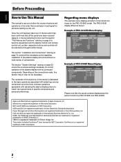
...and Screen Adjustment ......... 35 Picture Adjustment (1 35 Picture Adjustment (2 36 Picture Adjustment (3 37 Returning to operate the Plasma Display properly. PIONEER cannot assume liabilities for damage caused by qualified personnel with enough skill and competence. You will know how to the Original Picture Adjustment ...Safety Precautions" and these "Operating Instructions" carefully so you very much for Dealers: After installation, be sure to deliver this PIONEER product. English Notes on this manual in installation or mounting, misuse, modification or a natural disaster.
...and Screen Adjustment ......... 35 Picture Adjustment (1 35 Picture Adjustment (2 36 Picture Adjustment (3 37 Returning to operate the Plasma Display properly. PIONEER cannot assume liabilities for damage caused by qualified personnel with enough skill and competence. You will know how to the Original Picture Adjustment ...Safety Precautions" and these "Operating Instructions" carefully so you very much for Dealers: After installation, be sure to deliver this PIONEER product. English Notes on this manual in installation or mounting, misuse, modification or a natural disaster.
Owner's Manual
Page 6
..." starting on -screen settings necessary for both the PRO-1010HD and PRO-810HD. VESA and DDC are trademarks or registered trademarks of NEC Corporation. HDMI, the HDMI logo and High-Definition Multimedia Interface are registered trademarks of the sections in this manual is dedicated to the basic operations associated with selecting... Please note that would seem most logical for the PRO-1010HD model. Once the unit has been taken out of the box and it may not be referred to follow the course of actions and operations in this manual are the same for correct operation of the plasma ...
..." starting on -screen settings necessary for both the PRO-1010HD and PRO-810HD. VESA and DDC are trademarks or registered trademarks of NEC Corporation. HDMI, the HDMI logo and High-Definition Multimedia Interface are registered trademarks of the sections in this manual is dedicated to the basic operations associated with selecting... Please note that would seem most logical for the PRO-1010HD model. Once the unit has been taken out of the box and it may not be referred to follow the course of actions and operations in this manual are the same for correct operation of the plasma ...

Owner's Manual
Page 7
... those found on the remote control unit, the commands can save picture adjustment setting values for the section "PICTURE adjustment". English About operations in this manual Each operation is described in the picture when viewing a digital broadcast, playing a DVD etc. Each time you change from LOW 3 MID 3 HIGH, the effect becomes...
... those found on the remote control unit, the commands can save picture adjustment setting values for the section "PICTURE adjustment". English About operations in this manual Each operation is described in the picture when viewing a digital broadcast, playing a DVD etc. Each time you change from LOW 3 MID 3 HIGH, the effect becomes...
Owner's Manual
Page 14
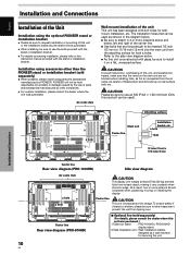
... Installation and Connections Installation of the Unit Installation using parts and accessories manufactured by PIONEER. The installation holes that can be inserted 1/2 inch (12 mm) to install... installation bracket. ÷ For details concerning installation, please refer to the instruction manual provided with glass, be sure to take measures to use an M8 (Pitch ...For custom installation, please consult the dealer where the unit was purchased.) 1 Table top stand : PRO-1010HD / PRO-810HD display stand. 2 Wall installation unit : Wall installation bracket designed as a wall interface for...
... Installation and Connections Installation of the Unit Installation using parts and accessories manufactured by PIONEER. The installation holes that can be inserted 1/2 inch (12 mm) to install... installation bracket. ÷ For details concerning installation, please refer to the instruction manual provided with glass, be sure to take measures to use an M8 (Pitch ...For custom installation, please consult the dealer where the unit was purchased.) 1 Table top stand : PRO-1010HD / PRO-810HD display stand. 2 Wall installation unit : Wall installation bracket designed as a wall interface for...

Owner's Manual
Page 18
... not displayed normally. Secure by tightening the terminal screws on the display and the personal computer's output terminal. For details, please read your PC's instruction manual or consult the maker or nearest dealer of the green signal. English Installation and Connections When connecting to ANALOG RGB IN (INPUT1) ANALOG RGB IN...
... not displayed normally. Secure by tightening the terminal screws on the display and the personal computer's output terminal. For details, please read your PC's instruction manual or consult the maker or nearest dealer of the green signal. English Installation and Connections When connecting to ANALOG RGB IN (INPUT1) ANALOG RGB IN...

Owner's Manual
Page 21
... with the DTV set top box. English Installation and Connections About DTV Set Top Box Connection To ensure proper connection, please carefully read the instruction manual supplied with are as follows. The set top box output signals that this display is possible INPUT1 INPUT1 INPUT2 INPUT3 INPUT4 INPUT5 (D-sub) (HDMI) Installation...
... with the DTV set top box. English Installation and Connections About DTV Set Top Box Connection To ensure proper connection, please carefully read the instruction manual supplied with are as follows. The set top box output signals that this display is possible INPUT1 INPUT1 INPUT2 INPUT3 INPUT4 INPUT5 (D-sub) (HDMI) Installation...

Owner's Manual
Page 23
... to INPUT3 or INPUT4 INPUT 3/4 AUDIO R L Installation and Connections Connecting Control Cords Connect control cords between this unit and other PIONEER equipment having the Î logo. About SR+ The CONTROL OUT terminal on the rear of this unit (because this unit does...the SPEAKER (L/R) terminals according to the video input selection. For more information, see the user's manual for a component connected to perform SR+ related function settings on your PIONEER AV receiver. Sound is no resistance). English Audio connection for component connected to INPUT5 INPUT5 AUDIO ...
... to INPUT3 or INPUT4 INPUT 3/4 AUDIO R L Installation and Connections Connecting Control Cords Connect control cords between this unit and other PIONEER equipment having the Î logo. About SR+ The CONTROL OUT terminal on the rear of this unit (because this unit does...the SPEAKER (L/R) terminals according to the video input selection. For more information, see the user's manual for a component connected to perform SR+ related function settings on your PIONEER AV receiver. Sound is no resistance). English Audio connection for component connected to INPUT5 INPUT5 AUDIO ...
Owner's Manual
Page 27
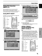
... : OFF : ON INPUT1 SELECT : D-SUB SR+ MODE : OFF 4 Use the 2/3 buttons to select [OPTION]. Adjustment for other signal frequency formats is performed automatically, so no manual setting is required (Setting [SIGNAL FORMAT] is not possible). ÷ The [COLOR DECODING] setting is not supported when inputting a computer signal, or when the [SIGNAL...
... : OFF : ON INPUT1 SELECT : D-SUB SR+ MODE : OFF 4 Use the 2/3 buttons to select [OPTION]. Adjustment for other signal frequency formats is performed automatically, so no manual setting is required (Setting [SIGNAL FORMAT] is not possible). ÷ The [COLOR DECODING] setting is not supported when inputting a computer signal, or when the [SIGNAL...

Owner's Manual
Page 28
... will cause the display mode to change alternately as follows: 3 480p 2 3 VGA 2 3 WVGA 2 24 EN 2 When providing input signals with WXGA inputs, set [SIGNAL FORMAT] manually to select the display mode.
... will cause the display mode to change alternately as follows: 3 480p 2 3 VGA 2 3 WVGA 2 24 EN 2 When providing input signals with WXGA inputs, set [SIGNAL FORMAT] manually to select the display mode.
Owner's Manual
Page 29
... S E T : LOCKED MENU E X I T The factory default setting is not possible when INPUT1 (D-sub), or INPUT3 through INPUT5 are selected. For details, please refer to the instruction manual supplied with [INPUT1 SELECT]. ÷ Setting is [AUTO]. Follow the procedures below and make settings as follows: 3 AUTO 2 3 LOCKED 2 5 Press the SET button. RGB video...
... S E T : LOCKED MENU E X I T The factory default setting is not possible when INPUT1 (D-sub), or INPUT3 through INPUT5 are selected. For details, please refer to the instruction manual supplied with [INPUT1 SELECT]. ÷ Setting is [AUTO]. Follow the procedures below and make settings as follows: 3 AUTO 2 3 LOCKED 2 5 Press the SET button. RGB video...

Owner's Manual
Page 30
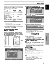
...7 After completing settings, press the MENU button to return to the normal display. In this event, select COLOR1, COLOR2, COLOR3 or COLOR4 manually in the picture when accepts RGB signals. S TA N D A R D INPUT1 PICTURE SCREEN SETUP PURECINEMA CLAMP POSITION SIGNAL FORMAT COLOR DECODING ... identifies input video signals. English System Settings PICTURE SELECT This function allows you to switch the input signal format to automatic or manual when inputting the digital signal. 1 Press the MENU button to remove white glare in accordance with some input signals. PICTURE SELECT...
...7 After completing settings, press the MENU button to return to the normal display. In this event, select COLOR1, COLOR2, COLOR3 or COLOR4 manually in the picture when accepts RGB signals. S TA N D A R D INPUT1 PICTURE SCREEN SETUP PURECINEMA CLAMP POSITION SIGNAL FORMAT COLOR DECODING ... identifies input video signals. English System Settings PICTURE SELECT This function allows you to switch the input signal format to automatic or manual when inputting the digital signal. 1 Press the MENU button to remove white glare in accordance with some input signals. PICTURE SELECT...

Owner's Manual
Page 31
... SET ENTER MENU EXIT 2 Use the 2/3 buttons to select [HDMI INPUT], then press the SET button. In this unit to connect another Pioneer product (Refer to page 19 for connection details). 1 Press the MENU button to display the menu screen. This completes [AUDIO] setting, and... INPUT2 PICTURE SCREEN SETUP PURECINEMA CLAMP POSITION SIGNAL FORMAT COLOR DECODING HDMI INPUT BRT. Each time you to switch the audio signal to automatic or manual when inputting the digital signal. 1 Press the MENU button to display the menu screen. Note Even when AUTO is required when using the CONTROL...
... SET ENTER MENU EXIT 2 Use the 2/3 buttons to select [HDMI INPUT], then press the SET button. In this unit to connect another Pioneer product (Refer to page 19 for connection details). 1 Press the MENU button to display the menu screen. This completes [AUDIO] setting, and... INPUT2 PICTURE SCREEN SETUP PURECINEMA CLAMP POSITION SIGNAL FORMAT COLOR DECODING HDMI INPUT BRT. Each time you to switch the audio signal to automatic or manual when inputting the digital signal. 1 Press the MENU button to display the menu screen. Note Even when AUTO is required when using the CONTROL...

Owner's Manual
Page 41
...of dark parts B. HIGH, R. LOW, G. automatically switches to display the menu. LOW, G. The values are not reflected if anything other than MANUAL/** is not possible when in the DYNAMIC mode in COLOR TEMP. HIGH, B. HIGH ... LOW ... Adjusts the green of dark parts Becomes softer... ... HIGH ... Adjusts the blue of dark parts G. Saves desired adjusted color temperature settings. The abbreviations of the color tone modes on which manual adjustments are based are reflected in [AV SELECTION]. ÷ If you press the 2/3 buttons, the setting changes as shown below. LOW ...
...of dark parts B. HIGH, R. LOW, G. automatically switches to display the menu. LOW, G. The values are not reflected if anything other than MANUAL/** is not possible when in the DYNAMIC mode in COLOR TEMP. HIGH, B. HIGH ... LOW ... Adjusts the green of dark parts Becomes softer... ... HIGH ... Adjusts the blue of dark parts G. Saves desired adjusted color temperature settings. The abbreviations of the color tone modes on which manual adjustments are based are reflected in [AV SELECTION]. ÷ If you press the 2/3 buttons, the setting changes as shown below. LOW ...
Owner's Manual
Page 43
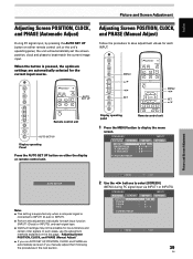
... unit. When the button is connected to INPUT1 (D-sub) or INPUT5. ÷ Perform this page, "Adjusting Screen POSITION, CLOCK, and PHASE (Manual Adjust)". ÷ If you run AUTO SET UP, POSITION, CLOCK and PHASE are automatically selected for each input function (INPUT1 (D-sub) or INPUT5...), and each INPUT. AUTO SET UP Adjusting Screen POSITION, CLOCK, and PHASE (Manual Adjust) Follow the procedure to best match the current image input. In such cases, use the adjustment methods explained on either remote control ...
... unit. When the button is connected to INPUT1 (D-sub) or INPUT5. ÷ Perform this page, "Adjusting Screen POSITION, CLOCK, and PHASE (Manual Adjust)". ÷ If you run AUTO SET UP, POSITION, CLOCK and PHASE are automatically selected for each input function (INPUT1 (D-sub) or INPUT5...), and each INPUT. AUTO SET UP Adjusting Screen POSITION, CLOCK, and PHASE (Manual Adjust) Follow the procedure to best match the current image input. In such cases, use the adjustment methods explained on either remote control ...


