
Service Manual
Page 1
GENERAL INFORMATION 48 7.1 DISASSEMBLY 48 7.2 PARTS 49 7.2.1 IC 49 7.2.2 DISPLAY 54 8. LTD. 253 Alexandra Road, #04-01, Singapore 159936 c PIONEER CORPORATION 2000 T - Type Model VSX-D409 VSX-D309 Power Requirement Remarks KUXJI AC120V KCXJI AC120V CONTENTS 1. Box 1760, Long Beach, CA 90801-1760, U.S.A. RRV2252 THIS MANUAL IS APPLICABLE TO THE FOLLOWING MODEL(S) AND TYPE(S). P.O. ...
GENERAL INFORMATION 48 7.1 DISASSEMBLY 48 7.2 PARTS 49 7.2.1 IC 49 7.2.2 DISPLAY 54 8. LTD. 253 Alexandra Road, #04-01, Singapore 159936 c PIONEER CORPORATION 2000 T - Type Model VSX-D409 VSX-D309 Power Requirement Remarks KUXJI AC120V KCXJI AC120V CONTENTS 1. Box 1760, Long Beach, CA 90801-1760, U.S.A. RRV2252 THIS MANUAL IS APPLICABLE TO THE FOLLOWING MODEL(S) AND TYPE(S). P.O. ...

Service Manual
Page 2
VSX-D409, VSX-D309 1. SAFETY INFORMATION This service manual is not meant for the continued protection of the appliance directly into a 120V AC 60Hz outlet and turn the AC power switch on PCB indicate that replacement parts must not exceed 0.5mA. Improperly performed repairs can be ... related characteristics. SAFETY PRECAUTIONS The following check should Leakage current not be obtained by connecting a leakage current tester such as the PIONEER recommended replacement one, shown in the parts list in the appliance have been trained to a known earth ground (water pipe, conduit...
VSX-D409, VSX-D309 1. SAFETY INFORMATION This service manual is not meant for the continued protection of the appliance directly into a 120V AC 60Hz outlet and turn the AC power switch on PCB indicate that replacement parts must not exceed 0.5mA. Improperly performed repairs can be ... related characteristics. SAFETY PRECAUTIONS The following check should Leakage current not be obtained by connecting a leakage current tester such as the PIONEER recommended replacement one, shown in the parts list in the appliance have been trained to a known earth ground (water pipe, conduit...
Service Manual
Page 5
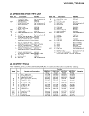
... SECTION PARTS LIST Mark No. Symbol and Description 1 D.D & INPUT Assy 4 AMP&PRIMARY Assy 5 REGULATOR Assy 10 Power Transformer (AC120V) 11 Fuse (FU1 : 10A) VSX-D409 /KUXJI AWX7649 AWX7480 AWX7467 ATS7264 REK1087 Part No. NSP 21 Fuse (FU701 : 10A) 22 23 Under Base 409 24...; AMP&PRIMARY CN53) 18 Strain Relief CM-22C 19 AC Power Cord ADG7024 20 Fuse (FU2) See Contrast table (2) Mark No. VSX-D409 /KCXJI AWX7649 AWX7480 AWX7467 ATS7264 REK1087 VSX-D309 /KUXJI AWX7494 AWX7506 AWX7493 ATS7263 Not used VSX-D309 /KCXJI AWX7494 AWX7506 AWX7493 ATS7263 Not used Remarks NSP 11...
... SECTION PARTS LIST Mark No. Symbol and Description 1 D.D & INPUT Assy 4 AMP&PRIMARY Assy 5 REGULATOR Assy 10 Power Transformer (AC120V) 11 Fuse (FU1 : 10A) VSX-D409 /KUXJI AWX7649 AWX7480 AWX7467 ATS7264 REK1087 Part No. NSP 21 Fuse (FU701 : 10A) 22 23 Under Base 409 24...; AMP&PRIMARY CN53) 18 Strain Relief CM-22C 19 AC Power Cord ADG7024 20 Fuse (FU2) See Contrast table (2) Mark No. VSX-D409 /KCXJI AWX7649 AWX7480 AWX7467 ATS7264 REK1087 VSX-D309 /KUXJI AWX7494 AWX7506 AWX7493 ATS7263 Not used VSX-D309 /KCXJI AWX7494 AWX7506 AWX7493 ATS7263 Not used Remarks NSP 11...
Service Manual
Page 7
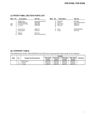
... Assy 3 R. ENCODER Assy 4 H.P. AAD7552 See Contrast table (2) PAM1776 PNW2019 PPZ30P080FMC ABA7009 (2) CONTRAST TABLE VSX-D409/KUXJI, KCXJI, VSX-D309/KUXJI and KCXJI are constructed the same except for the following : Mark No. See Contrast table (2) AWX7385 AWX7386 AWX7556 6 Volume Knob 7 Power Button 8 9 Window 10 F Button AAB7179 AAD7440 AAK7719 See Contrast table (2) Mark No. Description...
... Assy 3 R. ENCODER Assy 4 H.P. AAD7552 See Contrast table (2) PAM1776 PNW2019 PPZ30P080FMC ABA7009 (2) CONTRAST TABLE VSX-D409/KUXJI, KCXJI, VSX-D309/KUXJI and KCXJI are constructed the same except for the following : Mark No. See Contrast table (2) AWX7385 AWX7386 AWX7556 6 Volume Knob 7 Power Button 8 9 Window 10 F Button AAB7179 AAD7440 AAK7719 See Contrast table (2) Mark No. Description...
Service Manual
Page 11
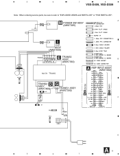
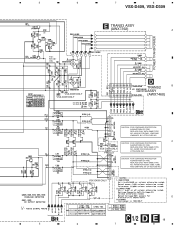
5 6 7 8 VSX-D409, VSX-D309 Note : When ordering service parts, be sure to refer to "EXPLODED VIEWS and PARTS LIST" or "PCB PARTS LIST". A M POWER SW ASSY (AWX7385) 471 501 403 551 I H.P. ASSY (AWX7556) E TRANS3 ASSY B (AWX7392) J6 J7 J3 A AMP INPUT ASSY (AWX7382) J5 J4 B 1/3 CN106 C 1/2 CN601 D TRANS2 ASSY (AWX7468) 851 G J2 J1 TRANS1 ASSY (AWX7390) C 701 D A 11 5 6 7 8
5 6 7 8 VSX-D409, VSX-D309 Note : When ordering service parts, be sure to refer to "EXPLODED VIEWS and PARTS LIST" or "PCB PARTS LIST". A M POWER SW ASSY (AWX7385) 471 501 403 551 I H.P. ASSY (AWX7556) E TRANS3 ASSY B (AWX7392) J6 J7 J3 A AMP INPUT ASSY (AWX7382) J5 J4 B 1/3 CN106 C 1/2 CN601 D TRANS2 ASSY (AWX7468) 851 G J2 J1 TRANS1 ASSY (AWX7390) C 701 D A 11 5 6 7 8

Service Manual
Page 13
5 6 : The power supply is shown with the marked box. H CN303 B 3/3 7 8 VSX-D409, VSX-D309 B 2/3 A B 3/3 K CN401 B A CN290 K CN402 C E-VR IC D B 2/3 B 3/3 B 1/3 13 5 6 7 8
5 6 : The power supply is shown with the marked box. H CN303 B 3/3 7 8 VSX-D409, VSX-D309 B 2/3 A B 3/3 K CN401 B A CN290 K CN402 C E-VR IC D B 2/3 B 3/3 B 1/3 13 5 6 7 8

Service Manual
Page 15
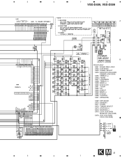
5 6 7 8 VSX-D409, VSX-D309 : The power supply is shown with the marked box. A MULTI CH CODEC IC B B 3/3 DTS DECODER IC 5 6 C D SRAM(256K) B 2/3 15 7 8
5 6 7 8 VSX-D409, VSX-D309 : The power supply is shown with the marked box. A MULTI CH CODEC IC B B 3/3 DTS DECODER IC 5 6 C D SRAM(256K) B 2/3 15 7 8
Service Manual
Page 19
... NO. 49101.6 FOR IC851, IC852 AND IC853 MFD, BY LITTELFUSE INC. CAUTION : FOR CONTINUED PROTECTION AGAINST RISK OF FIRE. 5 6 7 8 VSX-D409, VSX-D309 E TRANS3 ASSY (AWX7392) A POWER TRANSFORMER F701 : REK1087 (10A) VSX VSX -D309 -D409 VSX-D309 ONLY VSX-D409 ONLY VSX-D409 VSX-D309 D TRANS2 B ASSY (AWX7468) C 2/2 CAUTION : FOR CONTINUED PROTECTION AGAINST RISK OF FIRE. C CAUTION : FOR CONTINUED PROTECTION AGAINST RISK OF...
... NO. 49101.6 FOR IC851, IC852 AND IC853 MFD, BY LITTELFUSE INC. CAUTION : FOR CONTINUED PROTECTION AGAINST RISK OF FIRE. 5 6 7 8 VSX-D409, VSX-D309 E TRANS3 ASSY (AWX7392) A POWER TRANSFORMER F701 : REK1087 (10A) VSX VSX -D309 -D409 VSX-D309 ONLY VSX-D409 ONLY VSX-D409 VSX-D309 D TRANS2 B ASSY (AWX7468) C 2/2 CAUTION : FOR CONTINUED PROTECTION AGAINST RISK OF FIRE. C CAUTION : FOR CONTINUED PROTECTION AGAINST RISK OF...

Service Manual
Page 21
REPLACE WITH SAME TYPE AND RATINGS ONLY. D C 2/2 G 21 6 7 8 5 6 C 2/2 AMP&PRIMARY ASSY (VSX-D409 : AWX7480) (VSX-D309 : AWX7506) C 1/2 7 8 VSX-D409, VSX-D309 A POWER TRANSFORMER VSX-D409 : REK1086 (8A) VSX-D309 : REK1067 (5A) B G TRANS1 ASSY (AWX7390) C 1/2 5 C VSX-D409 : REK1087 (10A) VSX-D309 : REK1069 (6.3A) LIVE ATT7057 NEUTRAL AC POWER CORD ADG7024 • NOTE FOR FUSE REPLACEMENT CAUTION -FOR CONTINUED PROTECTION AGAINST RISK OF FIRE.
REPLACE WITH SAME TYPE AND RATINGS ONLY. D C 2/2 G 21 6 7 8 5 6 C 2/2 AMP&PRIMARY ASSY (VSX-D409 : AWX7480) (VSX-D309 : AWX7506) C 1/2 7 8 VSX-D409, VSX-D309 A POWER TRANSFORMER VSX-D409 : REK1086 (8A) VSX-D309 : REK1067 (5A) B G TRANS1 ASSY (AWX7390) C 1/2 5 C VSX-D409 : REK1087 (10A) VSX-D309 : REK1069 (6.3A) LIVE ATT7057 NEUTRAL AC POWER CORD ADG7024 • NOTE FOR FUSE REPLACEMENT CAUTION -FOR CONTINUED PROTECTION AGAINST RISK OF FIRE.
Service Manual
Page 25
5 6 SYSTEM CONTROL MCU 5 6 7 8 VSX-D409, VSX-D309 A VSX-D409 VSX-D309 M POWER SW ASSY (AWX7385) B FRONT ASSY S451 : DOLBY PRO LOGIC S452 : DSP MODE S453 : SIGNAL SELECT S454 : MONITOR (VSX-D409) DIMMER (VSX-D309) S455 : TREBLE (+) S456 : FM/AM S457 : LOUDNESS S458 : TREBLE (-) S459 : BASS (+) S460 : DVD 5.1CH S461 : TV/SAT S462 : CD ... VCR/DVR S467 : SPEAKERS C S469 : MPX MODE S470 : MEMORY S471 : CLASS S472 : TUNING SELECT S473 : STATION (+) S474 : STATION (-) S475 : CD-R (VSX-D409) MONITOR (VSX-D309) S476 : AUX (VSX-D409) CD-R (VSX-D309) I 551 D K M 25 7 8
5 6 SYSTEM CONTROL MCU 5 6 7 8 VSX-D409, VSX-D309 A VSX-D409 VSX-D309 M POWER SW ASSY (AWX7385) B FRONT ASSY S451 : DOLBY PRO LOGIC S452 : DSP MODE S453 : SIGNAL SELECT S454 : MONITOR (VSX-D409) DIMMER (VSX-D309) S455 : TREBLE (+) S456 : FM/AM S457 : LOUDNESS S458 : TREBLE (-) S459 : BASS (+) S460 : DVD 5.1CH S461 : TV/SAT S462 : CD ... VCR/DVR S467 : SPEAKERS C S469 : MPX MODE S470 : MEMORY S471 : CLASS S472 : TUNING SELECT S473 : STATION (+) S474 : STATION (-) S475 : CD-R (VSX-D409) MONITOR (VSX-D309) S476 : AUX (VSX-D409) CD-R (VSX-D309) I 551 D K M 25 7 8

Service Manual
Page 27
1 2 3 4 VSX-D409, VSX-D309 4.2 TRANS2, TRANS3, REGULATOR and TRANS1 ASSYS F REGULATOR ASSY A Q805 Q803 Q806 Q801 Q804 Q802 IC804 B CN101 B IC803 E TRANS3 ASSY C J6 J4 J3 J5 J7 IC802 IC801 H CN306 C CN53 POWER TRANSFORMER C G TRANS1 ASSY (ANP7331-B) SIDE A 1 D C J1 J2 D TRANS2 ASSY C 701 D E F G 27 2 3 4
1 2 3 4 VSX-D409, VSX-D309 4.2 TRANS2, TRANS3, REGULATOR and TRANS1 ASSYS F REGULATOR ASSY A Q805 Q803 Q806 Q801 Q804 Q802 IC804 B CN101 B IC803 E TRANS3 ASSY C J6 J4 J3 J5 J7 IC802 IC801 H CN306 C CN53 POWER TRANSFORMER C G TRANS1 ASSY (ANP7331-B) SIDE A 1 D C J1 J2 D TRANS2 ASSY C 701 D E F G 27 2 3 4
Service Manual
Page 39
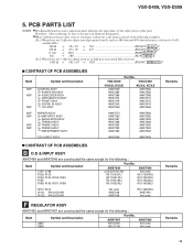
... INPUT ASSY REGULATOR ASSY TRANS2 ASSY TRANS1 ASSY TRANS3 ASSY AMP&PRIMARY ASSY D.D & INPUT ASSY Part No. VSX-D409, VSX-D309 Mark No. Description Part No. 5. VSX-D409 VSX-D309 /KUXJI, KCXJI /KUXJI, KCXJI AWK7569 AWX7385 AWX7386 AWX7474 AWX7479 AWX7505 AWX7556 AWK7565 AWX7385 AWX7386 AWX7474 AWX7475 AWX7476...; 5621 RN1/4PC 5 6 2 1 F CONTRAST OF PCB ASSEMBLIES Mark Symbol and Description NSP NSP NSP NSP NSP NSP NSP COMPLEX ASSY POWER SW ASSY R.ENCODER ASSY VIDEO&6CH IN ASSY FRONT ASSY DIGITAL IN ASSY H.P. Therefore, when replacing, be sure to use parts of the part...
... INPUT ASSY REGULATOR ASSY TRANS2 ASSY TRANS1 ASSY TRANS3 ASSY AMP&PRIMARY ASSY D.D & INPUT ASSY Part No. VSX-D409, VSX-D309 Mark No. Description Part No. 5. VSX-D409 VSX-D309 /KUXJI, KCXJI /KUXJI, KCXJI AWK7569 AWX7385 AWX7386 AWX7474 AWX7479 AWX7505 AWX7556 AWK7565 AWX7385 AWX7386 AWX7474 AWX7475 AWX7476...; 5621 RN1/4PC 5 6 2 1 F CONTRAST OF PCB ASSEMBLIES Mark Symbol and Description NSP NSP NSP NSP NSP NSP NSP COMPLEX ASSY POWER SW ASSY R.ENCODER ASSY VIDEO&6CH IN ASSY FRONT ASSY DIGITAL IN ASSY H.P. Therefore, when replacing, be sure to use parts of the part...

Service Manual
Page 47
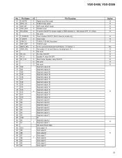
... RELAYS S511 ROTARY ENCODER OTHERS 511 CABLE HOLDER(3P) ASX7004 51063-0305 M POWER SW ASSY SEMICONDUCTORS D501 LED SWITCHES AND RELAYS S501 SWITCH RESISTORS R501 CHIP RESISTOR... D401 D403 TRANSISTOR TRANSISTOR TRANSISTOR CHIP DIODE ARRAY DIODE D404 D405 D407 D408 D442 CHIP DIODE ARRAY DIODE DIODE DIODE DIODE PDG247A KRA103M ... ELECT. CAPACITOR CKSQYB103K50 CEAT221M6R3 CKSQYB103K50 ACH7017 CEAT221M6R3 CKSQYB473K16 CKSQYB473K16 CKSQYB104K16 CEAT2R2M50 CEAT2R2M50 VSX-D409, VSX-D309 Mark No. CERAMIC CAPACITOR CKSQYB103K50 ELECT. CAPACITOR CEAT470M50 CERAMIC CAPACITOR CKSQYB104K16...
... RELAYS S511 ROTARY ENCODER OTHERS 511 CABLE HOLDER(3P) ASX7004 51063-0305 M POWER SW ASSY SEMICONDUCTORS D501 LED SWITCHES AND RELAYS S501 SWITCH RESISTORS R501 CHIP RESISTOR... D401 D403 TRANSISTOR TRANSISTOR TRANSISTOR CHIP DIODE ARRAY DIODE D404 D405 D407 D408 D442 CHIP DIODE ARRAY DIODE DIODE DIODE DIODE PDG247A KRA103M ... ELECT. CAPACITOR CKSQYB103K50 CEAT221M6R3 CKSQYB103K50 ACH7017 CEAT221M6R3 CKSQYB473K16 CKSQYB473K16 CKSQYB104K16 CEAT2R2M50 CEAT2R2M50 VSX-D409, VSX-D309 Mark No. CERAMIC CAPACITOR CKSQYB103K50 ELECT. CAPACITOR CEAT470M50 CERAMIC CAPACITOR CKSQYB104K16...

Service Manual
Page 48
Assy E TRANS 3 Assy G TRANS 1 Assy D TRANS 2 Assy J DIGITAL IN Assy C AMP&PRIMARY Assy VSX-D409, VSX-D309 7. GENERAL INFORMATION 7.1 DISASSEMBLY Diagnosis 1 Remove the Bonnet (seven screws). 2 ×3 2 ×2 2 ×2 2 ×3 2 ×2 Note : This photograph shows other models. However, the work method is the same. 4 Pull up Rear Panel 2 ×5 REGULATOR Assy 5 Diagnosis AMP&PRIMARY Assy Heat Sink 3 ×3 PCB Location L R. ENCODER Assy A AMP INPUT Assy B D.D & INPUT Assy H VIDEO&6CH IN Assy FM/AM TUNER Unit F REGULATOR Assy 48 K FRONT Assy M POWER SW Assy I H.P.
Assy E TRANS 3 Assy G TRANS 1 Assy D TRANS 2 Assy J DIGITAL IN Assy C AMP&PRIMARY Assy VSX-D409, VSX-D309 7. GENERAL INFORMATION 7.1 DISASSEMBLY Diagnosis 1 Remove the Bonnet (seven screws). 2 ×3 2 ×2 2 ×2 2 ×3 2 ×2 Note : This photograph shows other models. However, the work method is the same. 4 Pull up Rear Panel 2 ×5 REGULATOR Assy 5 Diagnosis AMP&PRIMARY Assy Heat Sink 3 ×3 PCB Location L R. ENCODER Assy A AMP INPUT Assy B D.D & INPUT Assy H VIDEO&6CH IN Assy FM/AM TUNER Unit F REGULATOR Assy 48 K FRONT Assy M POWER SW Assy I H.P.
Service Manual
Page 51
VSX-D409, VSX-D309 No. Pin Name 51 D_MUTE 52 9273_CS 53 DSP_MT 54 CDC_RST 55 FM+(RDS) 56 57 T_POWON 58 T_MUTE 59 9164 CS 60 DSP_RST ... G4 100 G3 I/O Pin Function O Digital mute (Not used) O TC9273 Chip select O DSP mute (ASSY mute) O CODEC reset O Tr switch ON/OFF for power supply of RDS decoder (L : AM, power OFF , H : Other) O Not used O Tuner module ON/OFF (North America model only) O Tuner mute O TC9163, TC9164 Chip select O YSS912 reset O 5.1ch, surround...
VSX-D409, VSX-D309 No. Pin Name 51 D_MUTE 52 9273_CS 53 DSP_MT 54 CDC_RST 55 FM+(RDS) 56 57 T_POWON 58 T_MUTE 59 9164 CS 60 DSP_RST ... G4 100 G3 I/O Pin Function O Digital mute (Not used) O TC9273 Chip select O DSP mute (ASSY mute) O CODEC reset O Tr switch ON/OFF for power supply of RDS decoder (L : AM, power OFF , H : Other) O Not used O Tuner module ON/OFF (North America model only) O Tuner mute O TC9163, TC9164 Chip select O YSS912 reset O 5.1ch, surround...
Service Manual
Page 53
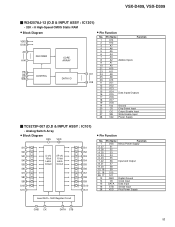
VSX-D409, VSX-D309 W24257AJ-12 (D.D & INPUT ASSY : IC1301) • 32K × 8 High-Speed CMOS Static RAM &#...DATA I/O 11 I/O1 19 I /O8 14 Vss Ground 20 CS Chip Select Input 22 OE Output Enable Input 27 WE Write Enable Input 28 Vdd Power Supply TC9273F-007 (D.D & INPUT ASSY : IC101) • Analog Switch Array • Block Diagram DSS VDD 1 28 S1 2 S2 3 S3...S6 S7 S8 S9 S10 S11 GND CK DATA STB VDD Function Minus Power Supply Input and Output Digital Ground Clock Input Data Input Strobe Input Plus Power Supply Level Shift + Shift Register Circuit 13 14 GND CK 15 16...
VSX-D409, VSX-D309 W24257AJ-12 (D.D & INPUT ASSY : IC1301) • 32K × 8 High-Speed CMOS Static RAM &#...DATA I/O 11 I/O1 19 I /O8 14 Vss Ground 20 CS Chip Select Input 22 OE Output Enable Input 27 WE Write Enable Input 28 Vdd Power Supply TC9273F-007 (D.D & INPUT ASSY : IC101) • Analog Switch Array • Block Diagram DSS VDD 1 28 S1 2 S2 3 S3...S6 S7 S8 S9 S10 S11 GND CK DATA STB VDD Function Minus Power Supply Input and Output Digital Ground Clock Input Data Input Strobe Input Plus Power Supply Level Shift + Shift Register Circuit 13 14 GND CK 15 16...
Service Manual
Page 56
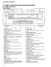
...in 2dB steps). $ TREBLE (+/-) buttons Use to increase/decrease treble (within a range of power (1W) in 2dB steps). % Function buttons Use to switch tape monitoring on or off. MONITOR button (VSX-D409) Press to select a source for recall using the tuner. Use to create different surround sound... quality and allow you to switch between the various DSP modes available (HALL1, HALL 2, JAZZ, DANCE, THEATER1, THEATER 2) and DSP off . ! VSX-D409, VSX-D309 8. SPEAKER button Use to switch the speaker system on or off. @ DIRECT button Use to 6dB in standby mode). 3 STATION (+/-), FREQUENCY ...
...in 2dB steps). $ TREBLE (+/-) buttons Use to increase/decrease treble (within a range of power (1W) in 2dB steps). % Function buttons Use to switch tape monitoring on or off. MONITOR button (VSX-D409) Press to select a source for recall using the tuner. Use to create different surround sound... quality and allow you to switch between the various DSP modes available (HALL1, HALL 2, JAZZ, DANCE, THEATER1, THEATER 2) and DSP off . ! VSX-D409, VSX-D309 8. SPEAKER button Use to switch the speaker system on or off. @ DIRECT button Use to 6dB in standby mode). 3 STATION (+/-), FREQUENCY ...
Service Manual
Page 57
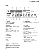
... 0dB indicates the maximum level. • Depending on the level settings you make for the current component (see "Front Panel", -, SIGNAL SELECT). VSX-D409, VSX-D309 Display 1 2 3 4 5 6 7 PRO LOGIC DSP MIDNIGHT DIGITAL ATT LOUDNESS SIGNAL SELECT ANALOG DIGITAL DIGITAL DTS DIRECT S.BASS MONITOR MONO TUNED...this lights to indicate playback of the input signal (can range between -10dB and 0dB. 57 Volume level is maintained even when the power is off . @ MASTER VOLUME LEVEL Shows the overall volume level. This function bypasses all tone, balance, DSP and Dolby Surround ...
... 0dB indicates the maximum level. • Depending on the level settings you make for the current component (see "Front Panel", -, SIGNAL SELECT). VSX-D409, VSX-D309 Display 1 2 3 4 5 6 7 PRO LOGIC DSP MIDNIGHT DIGITAL ATT LOUDNESS SIGNAL SELECT ANALOG DIGITAL DIGITAL DTS DIRECT S.BASS MONITOR MONO TUNED...this lights to indicate playback of the input signal (can range between -10dB and 0dB. 57 Volume level is maintained even when the power is off . @ MASTER VOLUME LEVEL Shows the overall volume level. This function bypasses all tone, balance, DSP and Dolby Surround ...

Service Manual
Page 59
...volumes. 9 FUNCTION button Use select the playback or recording source. The FQ +/- buttons Use to change channels on the loudness. VSX-D409, VSX-D309 4 THE FOLLOWING FOUR SETS OF BUTTONS ARE DEDICATED TV CONTROL. D. These buttons are three brightness settings as well as ...an off other components. 59 etc. 0 RECEIVER (POWER) button This switches between the three banks (classes) of the receiver in different DSP sound modes or advanced listening modes. ! 2 3 5&#...
...volumes. 9 FUNCTION button Use select the playback or recording source. The FQ +/- buttons Use to change channels on the loudness. VSX-D409, VSX-D309 4 THE FOLLOWING FOUR SETS OF BUTTONS ARE DEDICATED TV CONTROL. D. These buttons are three brightness settings as well as ...an off other components. 59 etc. 0 RECEIVER (POWER) button This switches between the three banks (classes) of the receiver in different DSP sound modes or advanced listening modes. ! 2 3 5&#...
Service Manual
Page 60
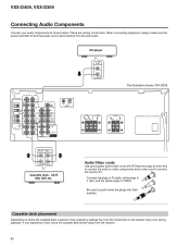
... 5.1 CH INPUT COAX OPT PCM/2/DTS DIGITAL IN CD player OUT L R The illustration shows VSX-D309. Be sure to VIDEO. When connecting equipment, always make sure the power switched off and the power cord is placed, noise caused by leakage flux from the transformer in the receiver may occur during... playback. Connect red plugs to R (right), white plugs to L (left), and the yellow plugs to push home the plugs into their sockets. VSX-D409, VSX-D309 ...
... 5.1 CH INPUT COAX OPT PCM/2/DTS DIGITAL IN CD player OUT L R The illustration shows VSX-D309. Be sure to VIDEO. When connecting equipment, always make sure the power switched off and the power cord is placed, noise caused by leakage flux from the transformer in the receiver may occur during... playback. Connect red plugs to R (right), white plugs to L (left), and the yellow plugs to push home the plugs into their sockets. VSX-D409, VSX-D309 ...


