
Service Manual
Page 1
... 3. PCB PARTS LIST 39 6. Box 1760, Long Beach, CA 90801-1760, U.S.A. LTD. 253 Alexandra Road, #04-01, Singapore 159936 c PIONEER CORPORATION 2000 T - SAFETY INFORMATION 2 2. GENERAL INFORMATION 48 7.1 DISASSEMBLY 48 7.2 PARTS 49 7.2.1 IC 49 7.2.2 DISPLAY 54 8. ZZK JAN.... Japan PHONES N∫m-Û≤?/ Digital Signal Processor MPX MODE 2/DTS SIGNAL SELECT R 1 MIDNIGHT @ @ AUDIO/VIDEO MULTI-CHANNEL RECEIVER VSX-D409 VSX-D309 ORDER NO. RRV2252 THIS MANUAL IS APPLICABLE TO THE FOLLOWING MODEL(S) AND TYPE(S). BLOCK DIAGRAM AND SCHEMATIC DIAGRAM ..... 8 4. ...
... 3. PCB PARTS LIST 39 6. Box 1760, Long Beach, CA 90801-1760, U.S.A. LTD. 253 Alexandra Road, #04-01, Singapore 159936 c PIONEER CORPORATION 2000 T - SAFETY INFORMATION 2 2. GENERAL INFORMATION 48 7.1 DISASSEMBLY 48 7.2 PARTS 49 7.2.1 IC 49 7.2.2 DISPLAY 54 8. ZZK JAN.... Japan PHONES N∫m-Û≤?/ Digital Signal Processor MPX MODE 2/DTS SIGNAL SELECT R 1 MIDNIGHT @ @ AUDIO/VIDEO MULTI-CHANNEL RECEIVER VSX-D409 VSX-D309 ORDER NO. RRV2252 THIS MANUAL IS APPLICABLE TO THE FOLLOWING MODEL(S) AND TYPE(S). BLOCK DIAGRAM AND SCHEMATIC DIAGRAM ..... 8 4. ...
Service Manual
Page 40
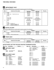
... AWX7506 and AWX7480 are constructed the same except for the following : Mark Symbol and Description C1901 R1901 JA1903 OPTICAL RECEIV MOD. AWX7479 AWX7475 R429 RS1/10S751J RS1/10S182J Remarks PCB PARTS LIST FOR VSX-D409 UNLESS OTHERWISE NOTED Mark No. Description A AMP INPUT ASSY OTHERS CN290 17P CONNECTOR CN291 16P SOCKET B D.D & INPUT... same except for the following : Mark Symbol and Description IC601 IC602 IC604-IC607 D758 RY754 PROTECTOR (10A) AWX7480 PAC010A PAC011A AEK7022 1SS133 ASR7001 Part No. VSX-D409, VSX-D309 Mark No. Mark No.
... AWX7506 and AWX7480 are constructed the same except for the following : Mark Symbol and Description C1901 R1901 JA1903 OPTICAL RECEIV MOD. AWX7479 AWX7475 R429 RS1/10S751J RS1/10S182J Remarks PCB PARTS LIST FOR VSX-D409 UNLESS OTHERWISE NOTED Mark No. Description A AMP INPUT ASSY OTHERS CN290 17P CONNECTOR CN291 16P SOCKET B D.D & INPUT... same except for the following : Mark Symbol and Description IC601 IC602 IC604-IC607 D758 RY754 PROTECTOR (10A) AWX7480 PAC010A PAC011A AEK7022 1SS133 ASR7001 Part No. VSX-D409, VSX-D309 Mark No. Mark No.

Service Manual
Page 47
... C532 CHIP CAPACITOR CERAMIC CAPACITOR CERAMIC CAPACITOR CKSQYB102K50 CKSQYB103K50 CKSQYB223K25 RESISTORS All Resistors RS1/10S&&&J OTHERS 401 403 471 491 REMOTE RECEIVER UNIT CABLE HOLDER(4P) CABLE HOLDER(4P) CABLE HOLDER(3P) GP1U27X 51063-0405 51063-0405 51063-0305 CN401 CN402 V401 ..., VSX-D309 Mark No. K FRONT ASSY SEMICONDUCTORS IC401 Q401 Q402 Q403 Q405 CONTROL MCU TRANSISTOR TRANSISTOR TRANSISTOR TRANSISTOR Q441 Q442 Q471 D401 D403 TRANSISTOR TRANSISTOR TRANSISTOR CHIP DIODE ARRAY DIODE D404 D405 D407 D408 D442 CHIP DIODE ARRAY DIODE DIODE DIODE DIODE PDG247A KRA103M...
... C532 CHIP CAPACITOR CERAMIC CAPACITOR CERAMIC CAPACITOR CKSQYB102K50 CKSQYB103K50 CKSQYB223K25 RESISTORS All Resistors RS1/10S&&&J OTHERS 401 403 471 491 REMOTE RECEIVER UNIT CABLE HOLDER(4P) CABLE HOLDER(4P) CABLE HOLDER(3P) GP1U27X 51063-0405 51063-0405 51063-0305 CN401 CN402 V401 ..., VSX-D309 Mark No. K FRONT ASSY SEMICONDUCTORS IC401 Q401 Q402 Q403 Q405 CONTROL MCU TRANSISTOR TRANSISTOR TRANSISTOR TRANSISTOR Q441 Q442 Q471 D401 D403 TRANSISTOR TRANSISTOR TRANSISTOR CHIP DIODE ARRAY DIODE D404 D405 D407 D408 D442 CHIP DIODE ARRAY DIODE DIODE DIODE DIODE PDG247A KRA103M...
Service Manual
Page 56
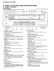
... AND SPECIFICATIONS 8.1 PANEL FACILITIES Front Panel The illustration shows VSX-D309. 1 23 4 56 7 8 9 0- = N∫m-Û≤?/ Digital Signal Processor R 1 MPX MODE 2/DTS SIGNAL SELECT PHONES MIDNIGHT @ @ ~ !@ # 1 STANDBY indicator Lights when the receiver is weak, press the MPX button to switch between on...jolted by loud or sudden sound effects. & FL DIMMER button (VSX-D309) Use this does not switch the speakers off . This feature will enable you to enjoy the broadcast. 7 Display 8 Remote sensor Receives the signals from any stereo source. 56 $% ^ & 0 ...
... AND SPECIFICATIONS 8.1 PANEL FACILITIES Front Panel The illustration shows VSX-D309. 1 23 4 56 7 8 9 0- = N∫m-Û≤?/ Digital Signal Processor R 1 MPX MODE 2/DTS SIGNAL SELECT PHONES MIDNIGHT @ @ ~ !@ # 1 STANDBY indicator Lights when the receiver is weak, press the MPX button to switch between on...jolted by loud or sudden sound effects. & FL DIMMER button (VSX-D309) Use this does not switch the speakers off . This feature will enable you to enjoy the broadcast. 7 Display 8 Remote sensor Receives the signals from any stereo source. 56 $% ^ & 0 ...
Service Manual
Page 57
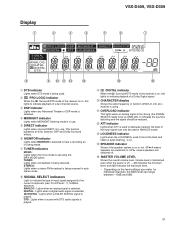
VSX-D409, VSX-D309 Display 1 2 3 4 5 6 7 PRO LOGIC DSP MIDNIGHT DIGITAL ATT LOUDNESS SIGNAL SELECT ANALOG DIGITAL DIGITAL DTS DIRECT S.BASS MONITOR MONO TUNED SP AB STEREO EON RDS RF ATT dB 8 9 0- = ~ 1 DTS indicator Lights when DTS mode is being used. 2 2 PRO LOGIC indicator When the 2 Surround/DTS mode of the receiver...being made. 7 TUNER indicators MONO: Lights when the mono mode is played. STEREO: Lights when a stereo FM broadcast is being received. DIGITAL : Lights when a digital audio signal is selected. 2 DIGITAL : Lights when a DOLBY DIGITAL signal is set using ...
VSX-D409, VSX-D309 Display 1 2 3 4 5 6 7 PRO LOGIC DSP MIDNIGHT DIGITAL ATT LOUDNESS SIGNAL SELECT ANALOG DIGITAL DIGITAL DTS DIRECT S.BASS MONITOR MONO TUNED SP AB STEREO EON RDS RF ATT dB 8 9 0- = ~ 1 DTS indicator Lights when DTS mode is being used. 2 2 PRO LOGIC indicator When the 2 Surround/DTS mode of the receiver...being made. 7 TUNER indicators MONO: Lights when the mono mode is played. STEREO: Lights when a stereo FM broadcast is being received. DIGITAL : Lights when a digital audio signal is selected. 2 DIGITAL : Lights when a DOLBY DIGITAL signal is set using ...

Service Manual
Page 58
... special functions. To use first press the RECEIVER button then operate this button. To use first press the RECEIVER button then operate this button. TEST TONE Use to put receiver in MIDNIGHT mode. CHANNEL LEVEL +/- To use first press the RECEIVER button then operate this button. VSX-D409, VSX-D309 Remote Control 1 2 3 4 5 6 7 8 9 0 - Î MULTI CONTROL DVD...
... special functions. To use first press the RECEIVER button then operate this button. To use first press the RECEIVER button then operate this button. TEST TONE Use to put receiver in MIDNIGHT mode. CHANNEL LEVEL +/- To use first press the RECEIVER button then operate this button. VSX-D409, VSX-D309 Remote Control 1 2 3 4 5 6 7 8 9 0 - Î MULTI CONTROL DVD...

Service Manual
Page 59
...menus/options and for deck 1 of the station you to switch between the three banks (classes) of memorized radio frequencies. The FQ +/- VSX-D409, VSX-D309 4 THE FOLLOWING FOUR SETS OF BUTTONS ARE DEDICATED TV CONTROL. TV CHANNEL +/- buttons can be used to add or subtract the amount... off other times, for this button brings you want. 8 LOUDNESS button Use to find radio frequencies. @ TOP MENU button In DVD mode this receiver. - buttons Use to set the overall listening volume. ^ REMOTE SETUP button Use this button to change channels on the loudness. Also, this is...
...menus/options and for deck 1 of the station you to switch between the three banks (classes) of memorized radio frequencies. The FQ +/- VSX-D409, VSX-D309 4 THE FOLLOWING FOUR SETS OF BUTTONS ARE DEDICATED TV CONTROL. TV CHANNEL +/- buttons can be used to add or subtract the amount... off other times, for this button brings you want. 8 LOUDNESS button Use to find radio frequencies. @ TOP MENU button In DVD mode this receiver. - buttons Use to set the overall listening volume. ^ REMOTE SETUP button Use this button to change channels on the loudness. Also, this is...
Service Manual
Page 60
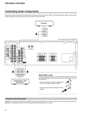
... MONITOR TV SUB WOOFER PREOUT SURROUND L CENTER DVD 5.1 CH INPUT COAX OPT PCM/2/DTS DIGITAL IN CD player OUT L R The illustration shows VSX-D309. FRONT SPEAKERS RL CENTER SPEAKER SURROUND SPEAKERS RL AC OUTLET PLAY REC L R Cassette deck , CD-R MD, DAT etc. These are ...analog connections. If you experience noise, move the cassette deck farther away from the transformer in the receiver may occur during playback. Cassette deck placement Depending on where the cassette deck is disconnected from the wall outlet. When connecting equipment, always ...
... MONITOR TV SUB WOOFER PREOUT SURROUND L CENTER DVD 5.1 CH INPUT COAX OPT PCM/2/DTS DIGITAL IN CD player OUT L R The illustration shows VSX-D309. FRONT SPEAKERS RL CENTER SPEAKER SURROUND SPEAKERS RL AC OUTLET PLAY REC L R Cassette deck , CD-R MD, DAT etc. These are ...analog connections. If you experience noise, move the cassette deck farther away from the transformer in the receiver may occur during playback. Cassette deck placement Depending on where the cassette deck is disconnected from the wall outlet. When connecting equipment, always ...

Service Manual
Page 61
...VOL FQ ST MENU ST ENTER TOP MENU FQ SOURCE CLASS MPX BAND 7 8 3 D.ACCESS 1¡ CHANNEL 4¢ LOUDNESS FUNCTION MUTING RECEIVER FL DIMMER REMOTE SETUP MASTER VOLUME AUDIO/VIDEO PRE-PROGRAMMED REMOTE CONTROL UNIT Remote control unit (AXD7246) 61 Confidential Unpublished Works. © ... "Dolby", "Pro Logic" and the double-D symbol are trademarks of Digital Theater Systems, Inc. © 1996 Digital Theater Systems, Inc. VSX-D409, VSX-D309 8.2 SPECIFICATIONS Amplifier Section Continuous average power output of 60 watts* per channel, min., at 8 ohms, from 40 Hz to 20,000...
...VOL FQ ST MENU ST ENTER TOP MENU FQ SOURCE CLASS MPX BAND 7 8 3 D.ACCESS 1¡ CHANNEL 4¢ LOUDNESS FUNCTION MUTING RECEIVER FL DIMMER REMOTE SETUP MASTER VOLUME AUDIO/VIDEO PRE-PROGRAMMED REMOTE CONTROL UNIT Remote control unit (AXD7246) 61 Confidential Unpublished Works. © ... "Dolby", "Pro Logic" and the double-D symbol are trademarks of Digital Theater Systems, Inc. © 1996 Digital Theater Systems, Inc. VSX-D409, VSX-D309 8.2 SPECIFICATIONS Amplifier Section Continuous average power output of 60 watts* per channel, min., at 8 ohms, from 40 Hz to 20,000...


