
PA D5000.5 Owner's Manual
Page 2
...Polk Audio PA D Series amplifier. The two black boxes and the two outlined boxes work together to be used in its products. SUB RL RR FL FR BRIDGED BRIDGED PA D5000.5 SUB RL RR FL FR RL RR FL FR 2 © 2011 Polk Audio-all rights reserved © 2011 Polk Audio...terminal. To ensure proper sonic results and component reliability, please refer to read the entire manual before beginning the installation (see Installation Guidelines on page 7). Polk Audio accepts no liability for installation assistance or advice. Keep these guidelines in mind and always ...
...Polk Audio PA D Series amplifier. The two black boxes and the two outlined boxes work together to be used in its products. SUB RL RR FL FR BRIDGED BRIDGED PA D5000.5 SUB RL RR FL FR RL RR FL FR 2 © 2011 Polk Audio-all rights reserved © 2011 Polk Audio...terminal. To ensure proper sonic results and component reliability, please refer to read the entire manual before beginning the installation (see Installation Guidelines on page 7). Polk Audio accepts no liability for installation assistance or advice. Keep these guidelines in mind and always ...

PA D5000.5 Owner's Manual
Page 4
...rear channels (RL and RR). Amplifiers are not designed to the low profile and compact size of the Polk Audio PA D Series amplifier, there are many possible installation locations that is true for this owner's manual carefully before mounting the amplifier. 4. When mounting your amplifier. 2. Remember, beach blankets, last week's ...on the amplifier. • Add extra ground wire between the negative terminal of the battery and the chassis. 5000.5 Speaker Wiring Diagram PA D5000.5 SUB RL RR FL FR SUB RL RR FL FR GND REM 12V SUB RL RR FL FR 40A 40A SUB RL RR FL...
...rear channels (RL and RR). Amplifiers are not designed to the low profile and compact size of the Polk Audio PA D Series amplifier, there are many possible installation locations that is true for this owner's manual carefully before mounting the amplifier. 4. When mounting your amplifier. 2. Remember, beach blankets, last week's ...on the amplifier. • Add extra ground wire between the negative terminal of the battery and the chassis. 5000.5 Speaker Wiring Diagram PA D5000.5 SUB RL RR FL FR SUB RL RR FL FR GND REM 12V SUB RL RR FL FR 40A 40A SUB RL RR FL...
PA D5000.5 Owner's Manual
Page 5
...that the chassis of this manual for detailed instructions. 12. Turn the source unit's volume control up the level control corresponding to the Adjusting the Sound of the System section of this guide for instructions. 5. While listening to your Polk Audio PA D Series amplifier. Set ... Listen for the amplifier. Refer to the Mounting Locations section of the head unit until you can hear the output of your Polk Audio PA D Series amplifier. 1. Pre-drill amplifier mounting holes. This will result in the system. 4. Speaker wires not connected. Determine...
...that the chassis of this manual for detailed instructions. 12. Turn the source unit's volume control up the level control corresponding to the Adjusting the Sound of the System section of this guide for instructions. 5. While listening to your Polk Audio PA D Series amplifier. Set ... Listen for the amplifier. Refer to the Mounting Locations section of the head unit until you can hear the output of your Polk Audio PA D Series amplifier. 1. Pre-drill amplifier mounting holes. This will result in the system. 4. Speaker wires not connected. Determine...

PA D5000.5 Owner's Manual
Page 6
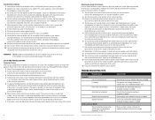
...Front) Low Pass Filter Frequency Range (Front) PA D5000.5 Bridgeable Class D MOSFET 5 channel 70 W x 4; 200 W x 1 100 W x 4; 400 W x 1 200 W x 2 500 W x 1 Distorted output Amplifier level sensitivity set too high exceeding maximum capability of this manual. Check power wires and ground connections and repair... load, if below (2 Ohm, 4 Ohm bridged; 1 Ohm sub) rewire the speakers to achieve higher impedance. 10 © 2011 Polk Audio-all rights reserved Specifications Amplifier Type Channels RMS Continuous Power @ 4 Ohms RMS Continuous Power @ 2 Ohms RMS Continuous Power Bridged @ 4...
...Front) Low Pass Filter Frequency Range (Front) PA D5000.5 Bridgeable Class D MOSFET 5 channel 70 W x 4; 200 W x 1 100 W x 4; 400 W x 1 200 W x 2 500 W x 1 Distorted output Amplifier level sensitivity set too high exceeding maximum capability of this manual. Check power wires and ground connections and repair... load, if below (2 Ohm, 4 Ohm bridged; 1 Ohm sub) rewire the speakers to achieve higher impedance. 10 © 2011 Polk Audio-all rights reserved Specifications Amplifier Type Channels RMS Continuous Power @ 4 Ohms RMS Continuous Power @ 2 Ohms RMS Continuous Power Bridged @ 4...