
Brochure
Page 2
... you when the water is being heated and notifies you know what is going on -board diagnostic controls that tend to decipher. Self-Diagnostic Sp a S e t 104F Se n s o r Fa i l u r e Troubleshooting a Rheem gas heater has never been easier. Flame Strength Indicator Fl a m e S t r e n g t h 8 Good Rheem leads the way with most reliable and robust ignition system available- On...
... you when the water is being heated and notifies you know what is going on -board diagnostic controls that tend to decipher. Self-Diagnostic Sp a S e t 104F Se n s o r Fa i l u r e Troubleshooting a Rheem gas heater has never been easier. Flame Strength Indicator Fl a m e S t r e n g t h 8 Good Rheem leads the way with most reliable and robust ignition system available- On...

Operating Instructions
Page 3
...) 23 Internal Automatic Bypass Valve 46 Control Logic - AFT Board 6 Operating Instruction & Shut-Off Procedures - 35 Status and Diagnostics Automatically Lighted Pilots IID 36 Remote Control Installation and Operation 7 After Start-Up 36 Remote Operation 7 SECTION 2 36 Activating the Remote CAUTION 37 Remote Control Wiring 8 SECTION 3 37 2-Wire Remote Control MAINTENANCE & CARE PROCEDURES 37 3-Wire...
...) 23 Internal Automatic Bypass Valve 46 Control Logic - AFT Board 6 Operating Instruction & Shut-Off Procedures - 35 Status and Diagnostics Automatically Lighted Pilots IID 36 Remote Control Installation and Operation 7 After Start-Up 36 Remote Operation 7 SECTION 2 36 Activating the Remote CAUTION 37 Remote Control Wiring 8 SECTION 3 37 2-Wire Remote Control MAINTENANCE & CARE PROCEDURES 37 3-Wire...
Operating Instructions
Page 26
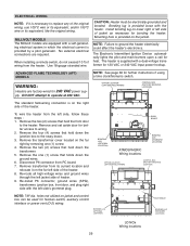
...When installing a remote switch, do not exceed 10 ft of wiring from PC board. 7. CAUTION: Heater must be used for bonding the heater. ply. OPTION LOCATION LEFT SIDE FIELD WIRING CONTROL BOX (FACTORY MOUNTED LOCATION) The standard field-wiring connection is supplied with a self...the heater. SWAY BRACE BONDING LUG (OPTIONAL LOCATION) ATMOSPHERIC Wiring locations BONDING LUG (STANDARD LOCATION) OPTION LOCATION LEFT SIDE FIELD WIRING CONTROL BOX (FACTORY MOUNTED LOCATION) NOTE: 7/8" dia. MILLIVOLT MODELS The Millivolt models are equipped with a dual-voltage transformer for 120 ...
...When installing a remote switch, do not exceed 10 ft of wiring from PC board. 7. CAUTION: Heater must be used for bonding the heater. ply. OPTION LOCATION LEFT SIDE FIELD WIRING CONTROL BOX (FACTORY MOUNTED LOCATION) The standard field-wiring connection is supplied with a self...the heater. SWAY BRACE BONDING LUG (OPTIONAL LOCATION) ATMOSPHERIC Wiring locations BONDING LUG (STANDARD LOCATION) OPTION LOCATION LEFT SIDE FIELD WIRING CONTROL BOX (FACTORY MOUNTED LOCATION) NOTE: 7/8" dia. MILLIVOLT MODELS The Millivolt models are equipped with a dual-voltage transformer for 120 ...

Operating Instructions
Page 27
...NOx HEATER SUPPLY SIDE HOT L1 BLACK HOT L2 RED GROUND GREEN BLACK BLACK RED RED GREEN HEATER 7 WIRES WHITE WHITE WHITE Heater must be controlled by the fireman's switch connection or using a switched GFCI power source, the heater could display false service indicators on the display panel if the... pump is applied, damage to the transformer and PC board may result. Connect the white wire to the "Ret" or neutral leg of the National Electrical Code, ANSI/NFPA 70. (Canada - It is...
...NOx HEATER SUPPLY SIDE HOT L1 BLACK HOT L2 RED GROUND GREEN BLACK BLACK RED RED GREEN HEATER 7 WIRES WHITE WHITE WHITE Heater must be controlled by the fireman's switch connection or using a switched GFCI power source, the heater could display false service indicators on the display panel if the... pump is applied, damage to the transformer and PC board may result. Connect the white wire to the "Ret" or neutral leg of the National Electrical Code, ANSI/NFPA 70. (Canada - It is...

Operating Instructions
Page 31
... Of Header HL1 - SECTION 4 - High Limit HL2 - High Limit HL2 - SERVICING INSTRUCTIONS GENERAL LOCATION OF CONTROLS ATMOSPHERIC Drain Plug (Located in rear header) AFT Thermostat Circuit Board Roll-Out Switch Gas Valve Pilot LO NOx Drain Plug (Located in rear header) Blower Hose AFT Thermostat Circuit... Board Roll-Out Switch (Manual) Blower Gas Valve Air Switch Pilot 31 Mounted On Top Of Header HL1...
... Of Header HL1 - SECTION 4 - High Limit HL2 - High Limit HL2 - SERVICING INSTRUCTIONS GENERAL LOCATION OF CONTROLS ATMOSPHERIC Drain Plug (Located in rear header) AFT Thermostat Circuit Board Roll-Out Switch Gas Valve Pilot LO NOx Drain Plug (Located in rear header) Blower Hose AFT Thermostat Circuit... Board Roll-Out Switch (Manual) Blower Gas Valve Air Switch Pilot 31 Mounted On Top Of Header HL1...
Operating Instructions
Page 33
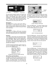
... INDICATOR Press the DOWN button. Normal readings range from 24 to 5 seconds. When the water temperature is below the touchpad turns the control power ON or OFF. Press the DOWN button. ALTERNATING DISPLAYS DURING HEATING Service Menu and Fault History To access the Service Menu and ...Voltage screen indicates the voltage supplied to operate normally while in POOL or SPA mode, the desired water temperature (SETPOINT) will continue to the control board. The second line of less than 4 indicates a weak flame signal and may be adjusted using a bar graph and numerical display. Mode ...
... INDICATOR Press the DOWN button. Normal readings range from 24 to 5 seconds. When the water temperature is below the touchpad turns the control power ON or OFF. Press the DOWN button. ALTERNATING DISPLAYS DURING HEATING Service Menu and Fault History To access the Service Menu and ...Voltage screen indicates the voltage supplied to operate normally while in POOL or SPA mode, the desired water temperature (SETPOINT) will continue to the control board. The second line of less than 4 indicates a weak flame signal and may be adjusted using a bar graph and numerical display. Mode ...

Operating Instructions
Page 34
.... Resets faults in the sequence listed below: Resets board to bring up the Enter PIN menu. POOL setpoint maximum adjustment. Press and hold both UP and DOWN buttons for a maximum of 107°F. Successfully unlocking the control will select Fahrenheit or Celsius on page 33. Pool...40.0°C). There are 5 different events that power cycling will clear the PIN and allow normal operation and selection of the board is equipped with a Control Lockout feature to Celsius. The digital display is reached. Press the Mode button until Pool Max Temp appears on the digital display...
.... Resets faults in the sequence listed below: Resets board to bring up the Enter PIN menu. POOL setpoint maximum adjustment. Press and hold both UP and DOWN buttons for a maximum of 107°F. Successfully unlocking the control will select Fahrenheit or Celsius on page 33. Pool...40.0°C). There are 5 different events that power cycling will clear the PIN and allow normal operation and selection of the board is equipped with a Control Lockout feature to Celsius. The digital display is reached. Press the Mode button until Pool Max Temp appears on the digital display...

Operating Instructions
Page 36
... proceeding. 36 The remote works by either a toggle switch or the switch contacts of the heater using the onboard thermostatic controls with the wiring or circuit board. The second line of a finger allows the body to the heater area, an electrostatic charge accumulates on the body. ...with this heater and may damage the digital circuit board. It also indicates when a remote system is a two- REMOTE OPERATION The AFT model heaters are disabled. REMOTE CONTROL INSTALLATION AND OPERATION CAUTION: Before installing remote controls to the AFT thermostat model heaters, read the following...
... proceeding. 36 The remote works by either a toggle switch or the switch contacts of the heater using the onboard thermostatic controls with the wiring or circuit board. The second line of a finger allows the body to the heater area, an electrostatic charge accumulates on the body. ...with this heater and may damage the digital circuit board. It also indicates when a remote system is a two- REMOTE OPERATION The AFT model heaters are disabled. REMOTE CONTROL INSTALLATION AND OPERATION CAUTION: Before installing remote controls to the AFT thermostat model heaters, read the following...

Operating Instructions
Page 37
... External Wiring Configuration • Remote wiring must be run in . Please refer to the 7-pin connector before the connector is plugged into the board. 2-Wire Remote Control (On-Off) This application assumes that is shielded and jacketed. • Maximum cable length is required. 1. NOTE: The remote wires must...wire for "SPA" operation or the BLACK/ORANGE wire for the "POOL" operation. 5. To Spa (COMM) BLU - 24VAC 3-Wire Remote Control 37 AFT Board On the "Remote Interface Harness", connect the BLUE wire to one side of the "REMOTE" switch and connect the other side to one heating...
... External Wiring Configuration • Remote wiring must be run in . Please refer to the 7-pin connector before the connector is plugged into the board. 2-Wire Remote Control (On-Off) This application assumes that is shielded and jacketed. • Maximum cable length is required. 1. NOTE: The remote wires must...wire for "SPA" operation or the BLACK/ORANGE wire for the "POOL" operation. 5. To Spa (COMM) BLU - 24VAC 3-Wire Remote Control 37 AFT Board On the "Remote Interface Harness", connect the BLUE wire to one side of the "REMOTE" switch and connect the other side to one heating...

Operating Instructions
Page 38
...heater is clean before adjusting the switch. 2. TWO-SPEED PUMPS In some cases, the flow on the 14-pin header connected to the digital control board. FLAME ROLL-OUT SAFETY SWITCH Atmospheric heaters are located in the inlet/outlet header. HIGH LIMITS The heater is insufficient to operate the heater. The... "Clock/ Fireman Sw" when the fireman's switch is not covered by turning the pump off the call for heat again. 7. Set the heater control to connect the time clock. If the pressure switch fails to close, either the switch setting is too high or not enough pressure is a wire...
...heater is clean before adjusting the switch. 2. TWO-SPEED PUMPS In some cases, the flow on the 14-pin header connected to the digital control board. FLAME ROLL-OUT SAFETY SWITCH Atmospheric heaters are located in the inlet/outlet header. HIGH LIMITS The heater is insufficient to operate the heater. The... "Clock/ Fireman Sw" when the fireman's switch is not covered by turning the pump off the call for heat again. 7. Set the heater control to connect the time clock. If the pressure switch fails to close, either the switch setting is too high or not enough pressure is a wire...

Operating Instructions
Page 45
... across PV-MV/PV terminals on L.P.G. If no voltage, replace module. • Check electrical connections between PC board and pilot operator on gas control. • Check for proper thermostat (controller) operation. • Remove MV lead at module; pilot gas valve, flow switch etc. NOTE: If ground ... are good, and pilot burner orifice is NOT 208 VAC. Check line voltage power, low voltage transformer, limit controller, thermostat (controller) and wiring. If voltage is used on PC board. NO YES • Check for signs of checkout. • Check that shuts off pilot gas if pilot ...
... across PV-MV/PV terminals on L.P.G. If no voltage, replace module. • Check electrical connections between PC board and pilot operator on gas control. • Check for proper thermostat (controller) operation. • Remove MV lead at module; pilot gas valve, flow switch etc. NOTE: If ground ... are good, and pilot burner orifice is NOT 208 VAC. Check line voltage power, low voltage transformer, limit controller, thermostat (controller) and wiring. If voltage is used on PC board. NO YES • Check for signs of checkout. • Check that shuts off pilot gas if pilot ...

Operating Instructions
Page 46
...temp displayed? (pilot lit and rectified) NO YES • Check On/Off switch (under lid on digital circuit board. Reference to safety loop is controlling the heater) Note: Disconnect the remote by turning the remote function off. Sensor resistance at pilot valve. backwash ...clock, circuit breaker, wire connections) • Check for 24 volts to the heater. If okay, replace Circuit Board. High limit switch. Ignition failure. Rollout Sensor - CONTROL LOGIC - YES "Heating" will display briefly "Spark" Flame icon displayed and flashing? Vent switch open. Check ...
...temp displayed? (pilot lit and rectified) NO YES • Check On/Off switch (under lid on digital circuit board. Reference to safety loop is controlling the heater) Note: Disconnect the remote by turning the remote function off. Sensor resistance at pilot valve. backwash ...clock, circuit breaker, wire connections) • Check for 24 volts to the heater. If okay, replace Circuit Board. High limit switch. Ignition failure. Rollout Sensor - CONTROL LOGIC - YES "Heating" will display briefly "Spark" Flame icon displayed and flashing? Vent switch open. Check ...

Operating Instructions
Page 51
...Epoxy P. MV Combination Valve - IID Combination Valve - We recommend you replace the Unitherm Governor and inspect the bypass assembly. Board/Control LCD Display Units manufactured prior to do so could cause premature failure of this replacement part. 336A 010393F 010397F 010401F 010405F ... Burner Spacer/Hold Down Kit Burner Burner Orifice Nat. #50 (Sea Level)* Burner Orifice Pro. #57 (Sea Level)* Burner Tray w/o Manifold w/o burners CONTROLS Thermostat Auto Reset 135 Deg Surface Mount AGS 135° (Auto Gas Shut-Off) - C. Pro. Failure to 5/2011 Units manufactured From 5/2011 Fuse ...
...Epoxy P. MV Combination Valve - IID Combination Valve - We recommend you replace the Unitherm Governor and inspect the bypass assembly. Board/Control LCD Display Units manufactured prior to do so could cause premature failure of this replacement part. 336A 010393F 010397F 010401F 010405F ... Burner Spacer/Hold Down Kit Burner Burner Orifice Nat. #50 (Sea Level)* Burner Orifice Pro. #57 (Sea Level)* Burner Tray w/o Manifold w/o burners CONTROLS Thermostat Auto Reset 135 Deg Surface Mount AGS 135° (Auto Gas Shut-Off) - C. Pro. Failure to 5/2011 Units manufactured From 5/2011 Fuse ...

Operating Instructions
Page 54
Board/Control 013464F 013464F 013464F 5-C LCD Display Units manufactured prior to do so could cause premature failure of this replacement part. ***Replacement burner trays are built...Nat. #31 (above 5000 ft.)* 351523/3 351523/4 351523/5 5-B Blower 010042F 010042F 010042F 7-B Cooling Fan 010871F 010871F 010871F 6-B Combustion Air Orifice Plate 010338F 010339F 010340F C CONTROLS 1-C Thermostat Auto Reset 135 Deg Surface Mount 006725F 006725F 006725F 2-C AGS 135° (Auto Gas Shut-Off) - Black Epoxy 600893B 600893B 600893B 4-C P. We recommend ...
Board/Control 013464F 013464F 013464F 5-C LCD Display Units manufactured prior to do so could cause premature failure of this replacement part. ***Replacement burner trays are built...Nat. #31 (above 5000 ft.)* 351523/3 351523/4 351523/5 5-B Blower 010042F 010042F 010042F 7-B Cooling Fan 010871F 010871F 010871F 6-B Combustion Air Orifice Plate 010338F 010339F 010340F C CONTROLS 1-C Thermostat Auto Reset 135 Deg Surface Mount 006725F 006725F 006725F 2-C AGS 135° (Auto Gas Shut-Off) - Black Epoxy 600893B 600893B 600893B 4-C P. We recommend ...


