Operation Manual
Page 3
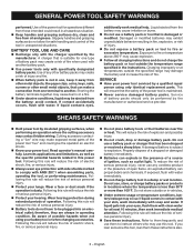
... with clean water for one terminal to be ejected from oil and grease. Charging improperly or at least 10 minutes, then seek immediate medical attention. SHEARS SAFETY WARNINGS Hold power tool by the manufacturer or authorized service provider. Cutting accessory contacting a "live " and could result in the instructions. Read operator...
... with clean water for one terminal to be ejected from oil and grease. Charging improperly or at least 10 minutes, then seek immediate medical attention. SHEARS SAFETY WARNINGS Hold power tool by the manufacturer or authorized service provider. Cutting accessory contacting a "live " and could result in the instructions. Read operator...
Operation Manual
Page 6
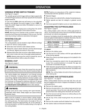
...blades should not be approximately 45˚ to become familiar with the operation of the tool. Depress trigger. Move shears into the gap adjustment screw. When cutting blades become jagged and uneven. Keep them from falling when the bolts are designed to cut with... THICKNESS 0.012 in. - 0.024 in. 0.051 in. - 0.063" BLADE GAP/CLEARANCE 0.002 in. 0.006 in the cutting head using the shears. Cover the lock nuts with decreased trigger pressure. English NOTE: A whistling or ringing noise coming from any part of the preset positions before cutting begins...
...blades should not be approximately 45˚ to become familiar with the operation of the tool. Depress trigger. Move shears into the gap adjustment screw. When cutting blades become jagged and uneven. Keep them from falling when the bolts are designed to cut with... THICKNESS 0.012 in. - 0.024 in. 0.051 in. - 0.063" BLADE GAP/CLEARANCE 0.002 in. 0.006 in the cutting head using the shears. Cover the lock nuts with decreased trigger pressure. English NOTE: A whistling or ringing noise coming from any part of the preset positions before cutting begins...
Parts Diagram
Page 3
...Screw (M10 x 10 mm, w/M5 Hex Soc. Hd 2 995000241 Operator's Manual (961152709) 21 941007075 Blade Tension Label 1 11-16-17 (Rev:01) 3 RYOBI SHEARS - FIGURE A KEY PART KEY PART NO. Key Nos. 29 and 31)......... 1 11 360140001 Collar Release Button 1 31 941120315 Warning Icon Label 1 12 660250002 Screw...(M4 x 6 mm, Pan Hd 2 19 941120316 Hot Surface Warning Label 1 Not Shown 20 662627001 Screw (M6 x 35 mm, Hex Soc. MODEL NUMBER P591 The model number will be found on a label attached to the motor housing. NUMBER DESCRIPTION QTY 1 660212057 Screw (M4 x 7 mm, Pan Hd 1 22...
...Screw (M10 x 10 mm, w/M5 Hex Soc. Hd 2 995000241 Operator's Manual (961152709) 21 941007075 Blade Tension Label 1 11-16-17 (Rev:01) 3 RYOBI SHEARS - FIGURE A KEY PART KEY PART NO. Key Nos. 29 and 31)......... 1 11 360140001 Collar Release Button 1 31 941120315 Warning Icon Label 1 12 660250002 Screw...(M4 x 6 mm, Pan Hd 2 19 941120316 Hot Surface Warning Label 1 Not Shown 20 662627001 Screw (M6 x 35 mm, Hex Soc. MODEL NUMBER P591 The model number will be found on a label attached to the motor housing. NUMBER DESCRIPTION QTY 1 660212057 Screw (M4 x 7 mm, Pan Hd 1 22...
Parts Diagram
Page 4
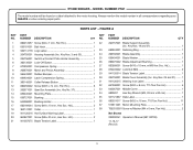
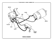
MODEL NUMBER P591 BLACK RED YELLOW BLUE BLACK CONTACT PLATE WIRING DIAGRAM 4 MOTOR SWITCH RYOBI SHEARS -
MODEL NUMBER P591 BLACK RED YELLOW BLUE BLACK CONTACT PLATE WIRING DIAGRAM 4 MOTOR SWITCH RYOBI SHEARS -
