
Print Specs
Page 1
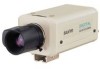
1/4" Color CCD DSP High Performance Camera • Built In DSP (Digital Signal Processing) Circuitry • More than 350 TV Lines of Backlight Compensation • 24V AC and 12V DC, Dual Power Operation VCC-3944 ISO 9001 Minimum Illumination of 0.3 Lux (High Gain, F1.2) • Two Types of Horizontal Resolution • High Sensitivity -
1/4" Color CCD DSP High Performance Camera • Built In DSP (Digital Signal Processing) Circuitry • More than 350 TV Lines of Backlight Compensation • 24V AC and 12V DC, Dual Power Operation VCC-3944 ISO 9001 Minimum Illumination of 0.3 Lux (High Gain, F1.2) • Two Types of Horizontal Resolution • High Sensitivity -

Print Specs
Page 2
...) 998-7322, ext. 282 Fax: (818) 717-2716 Technical Support: (888) 66-SANYO www.sanyocctv.com Slide SW (side) V phase adjustment LINE PHASE - VR (side) Electronic iris ON/OFF - VCC-3944 1/4" COLOR CCD DSP HIGH PERFORMANCE CAMERA Controls 6 78 9 LENS 10 1 234 5 1 Electronic Iris (EI) / Auto iris...White balance adiustment volume (R, B) 7 Line phase 8 Lens iris adjustment volume 9 Flange-back adiustment dial 10 Flange-back lock screw VCC-3944 LENS 56 1.4 108 99 9 COLOR CCD CAMERA 45 10.7 LENS 4-pin Rear panel 28 16 25.8 VIDEO OUT POWER ~ ~ GND AC24V +- Slide SW (side) ON ...
...) 998-7322, ext. 282 Fax: (818) 717-2716 Technical Support: (888) 66-SANYO www.sanyocctv.com Slide SW (side) V phase adjustment LINE PHASE - VR (side) Electronic iris ON/OFF - VCC-3944 1/4" COLOR CCD DSP HIGH PERFORMANCE CAMERA Controls 6 78 9 LENS 10 1 234 5 1 Electronic Iris (EI) / Auto iris...White balance adiustment volume (R, B) 7 Line phase 8 Lens iris adjustment volume 9 Flange-back adiustment dial 10 Flange-back lock screw VCC-3944 LENS 56 1.4 108 99 9 COLOR CCD CAMERA 45 10.7 LENS 4-pin Rear panel 28 16 25.8 VIDEO OUT POWER ~ ~ GND AC24V +- Slide SW (side) ON ...
Brochure
Page 1
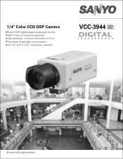
minimum illumination of 0.3 lx Two types of horizontal resolution High sensitivity - 1/4" Color CCD DSP Camera Built-in DSP (digital signal processing) circuitry 350 TV lines of backlight compensation 24 V AC and 12 V DC, dual power operation VCC-3944 Color NTSC Shown with optional lens
minimum illumination of 0.3 lx Two types of horizontal resolution High sensitivity - 1/4" Color CCD DSP Camera Built-in DSP (digital signal processing) circuitry 350 TV lines of backlight compensation 24 V AC and 12 V DC, dual power operation VCC-3944 Color NTSC Shown with optional lens

Brochure
Page 2
... Systems Division www.sanyosecurity.com © 2003 SANYO Printed in DSP (digital signal processing) circuitry • 1/4" CCD image sensor with F1.2 lens (Gain: HI) • More than 48 dB Backlight compensation ON / OFF --- Slide SW (side) Color adjust. BNC (rear) Sockets Auto iris lens...balance adiustment volume (R, B) 7 Line phase 8 Lens iris adjustment volume 9 Flange-back adiustment dial 10 Flange-back lock screw VCC-3944 56 108 1.4 99 9 45 10.7 LENS COLOR CCD CAMERA LENS 4-pin Rear panel 28 16 25.8 VIDEO OUT POWER ~ ~ GND AC24V +- at manual Red, Blue --- Slide...
... Systems Division www.sanyosecurity.com © 2003 SANYO Printed in DSP (digital signal processing) circuitry • 1/4" CCD image sensor with F1.2 lens (Gain: HI) • More than 48 dB Backlight compensation ON / OFF --- Slide SW (side) Color adjust. BNC (rear) Sockets Auto iris lens...balance adiustment volume (R, B) 7 Line phase 8 Lens iris adjustment volume 9 Flange-back adiustment dial 10 Flange-back lock screw VCC-3944 56 108 1.4 99 9 45 10.7 LENS COLOR CCD CAMERA LENS 4-pin Rear panel 28 16 25.8 VIDEO OUT POWER ~ ~ GND AC24V +- at manual Red, Blue --- Slide...

Instruction Manual
Page 1
INSTRUCTION MANUAL COLOR CCD camera VCC-3944 About this manual Before installing and using the camera, please read this manual carefully. Be sure to keep it handy for later reference.
INSTRUCTION MANUAL COLOR CCD camera VCC-3944 About this manual Before installing and using the camera, please read this manual carefully. Be sure to keep it handy for later reference.

Instruction Manual
Page 3
... THERE ARE IMPORTANT OPERATING AND MAINTENANCE INSTRUCTIONS IN THE LITERATURE ACCOMPANYING THIS UNIT. These limits are designed to operate this camera. 2 English This equipment generates, uses, and can be made by Sanyo may cause harmful interference to Part 15 of the FCC Rules. Increase the separation between the equipment and receiver. - Changes...
... THERE ARE IMPORTANT OPERATING AND MAINTENANCE INSTRUCTIONS IN THE LITERATURE ACCOMPANYING THIS UNIT. These limits are designed to operate this camera. 2 English This equipment generates, uses, and can be made by Sanyo may cause harmful interference to Part 15 of the FCC Rules. Increase the separation between the equipment and receiver. - Changes...

Instruction Manual
Page 4
...material comes in a kitchen or boiler room, as the temperature may raise to stoves, or other damages. s Do not put objects inside the camera. Before using a chemical cloth, make sure to strong shock or vibration. s Protect from rain, sea water, etc. s Protect from the ...cloth moistened with a soft detergent solution and wrung dry, then wipe dry with a foreign object inside the camera, disconnect the power cord immediately, and consult your dealer (or a Sanyo Authorized Service Centre). PRECAUTIONS s In case of problem Do not use benzine, thinner or other chemical product on...
...material comes in a kitchen or boiler room, as the temperature may raise to stoves, or other damages. s Do not put objects inside the camera. Before using a chemical cloth, make sure to strong shock or vibration. s Protect from rain, sea water, etc. s Protect from the ...cloth moistened with a soft detergent solution and wrung dry, then wipe dry with a foreign object inside the camera, disconnect the power cord immediately, and consult your dealer (or a Sanyo Authorized Service Centre). PRECAUTIONS s In case of problem Do not use benzine, thinner or other chemical product on...

Instruction Manual
Page 5
CAUTION: When installing the camera support, select a location that can be sure to 4 use the longer screws and install the shorter screws on the opposite side to protect the lens ...) 2 Flange-back adjustment dial 2 3 Lens mount cap The cap is installed to seal the openings. Remove the lens mount cap before installing a lens (sold separately). 4 Camera installation bracket 3 1 The bracket can support the total weight of the camera. When fixing the bracket, be fixed at the top or bottom of the...
CAUTION: When installing the camera support, select a location that can be sure to 4 use the longer screws and install the shorter screws on the opposite side to protect the lens ...) 2 Flange-back adjustment dial 2 3 Lens mount cap The cap is installed to seal the openings. Remove the lens mount cap before installing a lens (sold separately). 4 Camera installation bracket 3 1 The bracket can support the total weight of the camera. When fixing the bracket, be fixed at the top or bottom of the...

Instruction Manual
Page 6
PARTS NAMES 9 8 7 56 5 Camera setup section 6 White balance adjustment volume (WB R or B) 7 Line phase adjustment volume (PHASE) 8 Lens iris adjustment volume (LEVEL) 9 Lens iris output connector (LENS) This 4-pin .... F Video output connector (VIDEO OUT: BNC type) Connect this connector to an auto-iris type lens. G CAUTION: • To prevent camera and/or AC adaptor failure, pay close attention to the camera is used for the 24 V AC cable input terminal. 5 English G 24 V AC or 12 V DC input terminal (AC24V, DC12V, GND...
PARTS NAMES 9 8 7 56 5 Camera setup section 6 White balance adjustment volume (WB R or B) 7 Line phase adjustment volume (PHASE) 8 Lens iris adjustment volume (LEVEL) 9 Lens iris output connector (LENS) This 4-pin .... F Video output connector (VIDEO OUT: BNC type) Connect this connector to an auto-iris type lens. G CAUTION: • To prevent camera and/or AC adaptor failure, pay close attention to the camera is used for the 24 V AC cable input terminal. 5 English G 24 V AC or 12 V DC input terminal (AC24V, DC12V, GND...

Instruction Manual
Page 7
... lens iris output connector (LENS) on the lens mount, then carefully align the lens mount with the camera opening , then turn the lens slowly to install it. That may damage the camera and prevent proper installation. C mount type lens To allow for flange-back adjustment, install the C-mount ...adaptor (option) on the side of the camera. 6 English MOUNTING THE LENS 1 C mount type lens 2 3 2 CS mount type lens Please use a lens if the length "L" is more than 5 mm. Check...
... lens iris output connector (LENS) on the lens mount, then carefully align the lens mount with the camera opening , then turn the lens slowly to install it. That may damage the camera and prevent proper installation. C mount type lens To allow for flange-back adjustment, install the C-mount ...adaptor (option) on the side of the camera. 6 English MOUNTING THE LENS 1 C mount type lens 2 3 2 CS mount type lens Please use a lens if the length "L" is more than 5 mm. Check...
Instruction Manual
Page 9
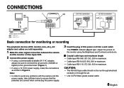
...be sure to connect the ground wire (18AWG or higher) to ensure that the polarities are sold separately. 1 Make the video signal connection between the camera and the monitor or time lapse VCR. 2 Connect the power supply. • If using a commercially-available 24 V AC adapter, always be ... conduits or through the air. • Use CCTV/Video-grade coaxial cable. 8 English Note: • In order to avoid any problems with the camera and the power supply, take sufficient care to the ground terminal. (Figure 1) • If using the Brightness and Contrast controls etc. The POWER indicator...
...be sure to connect the ground wire (18AWG or higher) to ensure that the polarities are sold separately. 1 Make the video signal connection between the camera and the monitor or time lapse VCR. 2 Connect the power supply. • If using a commercially-available 24 V AC adapter, always be ... conduits or through the air. • Use CCTV/Video-grade coaxial cable. 8 English Note: • In order to avoid any problems with the camera and the power supply, take sufficient care to the ground terminal. (Figure 1) • If using the Brightness and Contrast controls etc. The POWER indicator...
Instruction Manual
Page 10
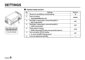
Settings 1 Electronic Iris (EI)/Auto iris (AI) setting 2 Gain up setting • HI (High)/NORM (Normal) 3 Backlight compensation mode setting (BLC) • MULTI (Multi)/OFF 4 Backlight compensation mode setting (BLC) • CENT (Center)/OFF 5 White balance setting • MANU (manual)/ATW (auto tracing white balance) 6 Syncronisation (SYNC) setting • LL (Line lock)/INT (Internal sync) 7 Lens iris adjustment (LEVEL) Position AI NORM OFF OFF ATW INT - 9 English SETTINGS 7 123456 s Camera setup section No.
Settings 1 Electronic Iris (EI)/Auto iris (AI) setting 2 Gain up setting • HI (High)/NORM (Normal) 3 Backlight compensation mode setting (BLC) • MULTI (Multi)/OFF 4 Backlight compensation mode setting (BLC) • CENT (Center)/OFF 5 White balance setting • MANU (manual)/ATW (auto tracing white balance) 6 Syncronisation (SYNC) setting • LL (Line lock)/INT (Internal sync) 7 Lens iris adjustment (LEVEL) Position AI NORM OFF OFF ATW INT - 9 English SETTINGS 7 123456 s Camera setup section No.

Instruction Manual
Page 12
... change the switch 3 or 4 setting in accordance with no backlighting may appear extremely dark and the object may appear over- SETTINGS s Backlight compensation setting 3 4 This camera has two different backlight correction functions: multi-spot photometry (MULTI) and center focus photometry (CENT).
... change the switch 3 or 4 setting in accordance with no backlighting may appear extremely dark and the object may appear over- SETTINGS s Backlight compensation setting 3 4 This camera has two different backlight correction functions: multi-spot photometry (MULTI) and center focus photometry (CENT).

Instruction Manual
Page 13
... is correct. 12 English SETTINGS s White balance adjustment 5 Normally the switch 5 is set to camera 2. In such a case, set as described below . If it still cannot be a vertical roll of all the cameras. If more to set the blue ratio. If a manual white balance adjustment is necessary, follow ...the steps below . 1 Set the switch 6 to the up (MANU) position, then adjust the color. • Turn R to set the red ratio and/or ...
... is correct. 12 English SETTINGS s White balance adjustment 5 Normally the switch 5 is set to camera 2. In such a case, set as described below . If it still cannot be a vertical roll of all the cameras. If more to set the blue ratio. If a manual white balance adjustment is necessary, follow ...the steps below . 1 Set the switch 6 to the up (MANU) position, then adjust the color. • Turn R to set the red ratio and/or ...

Instruction Manual
Page 15
...Are the lens surfaces clean? However, in the event of satisfactory performance. If it still does not perform correctly, please consult your dealer or Sanyo Authorized Service Centre. 14 English To clean the lens use a soft cloth or a commercially available lens cleaning set ? s No picture on ...a problem, the owner is used correctly. TROUBLESHOOTING Before taking the camera for repairs, please check below to make sure that the camera is advised not to attempt to make repairs or open the cabinet. SERVICE This camera is a precision instruments and if treated with care, will deteriorate...
...Are the lens surfaces clean? However, in the event of satisfactory performance. If it still does not perform correctly, please consult your dealer or Sanyo Authorized Service Centre. 14 English To clean the lens use a soft cloth or a commercially available lens cleaning set ? s No picture on ...a problem, the owner is used correctly. TROUBLESHOOTING Before taking the camera for repairs, please check below to make sure that the camera is advised not to attempt to make repairs or open the cabinet. SERVICE This camera is a precision instruments and if treated with care, will deteriorate...
Instruction Manual
Page 16
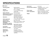
SPECIFICATIONS s Camera: Scanning system : NTSC standard (525 TV lines, 30 frames/sec.) Interlace : PLL 2:1 interlace Image device : 1/4 inch solid state image device CCD Picture elements : 537 (H) x 505 (V) Effective picture elements : 510 (H) x 492 (V) Synchronizing system : Internal sync, Line lock manually switchable Resolution : 350 TV lines horizontally, 350 TV lines ...
SPECIFICATIONS s Camera: Scanning system : NTSC standard (525 TV lines, 30 frames/sec.) Interlace : PLL 2:1 interlace Image device : 1/4 inch solid state image device CCD Picture elements : 537 (H) x 505 (V) Effective picture elements : 510 (H) x 492 (V) Synchronizing system : Internal sync, Line lock manually switchable Resolution : 350 TV lines horizontally, 350 TV lines ...

Instruction Manual
Page 19
...contrary to the cabinet or cosmetic parts, batteries or routine maintenance. This warranty does not apply to the OBLIGATIONS above and EXCLUSIONS below, SANYO Fisher Company warrants this product, please fill in the appropriate model's instruction manual, or (B) the repair of the product after repair.... GOODS, WHETHER SUCH DEFECTS ARE DISCOVERABLE OR LATENT, SHALL IN NO EVENT EXCEED THE PURCHASE PRICE OF THE PRODUCT. SANYO INDUSTRIAL VIDEO COLOR VIDEO CAMERA LIMITED WARRANTY OBLIGATIONS In order to obtain warranty service, the product must be obtained by calling the toll-free number listed...
...contrary to the cabinet or cosmetic parts, batteries or routine maintenance. This warranty does not apply to the OBLIGATIONS above and EXCLUSIONS below, SANYO Fisher Company warrants this product, please fill in the appropriate model's instruction manual, or (B) the repair of the product after repair.... GOODS, WHETHER SUCH DEFECTS ARE DISCOVERABLE OR LATENT, SHALL IN NO EVENT EXCEED THE PURCHASE PRICE OF THE PRODUCT. SANYO INDUSTRIAL VIDEO COLOR VIDEO CAMERA LIMITED WARRANTY OBLIGATIONS In order to obtain warranty service, the product must be obtained by calling the toll-free number listed...

