CV-P09LX , CV-P10LC , CV-P10MX , CV-P12LX Operation Manual
Page 3
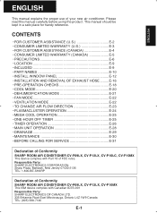
...8226; MAINTENANCE E-30 • BEFORE CALLING FOR SERVICE E-31 Declaration of Conformity SHARP ROOM AIR CONDITIONER CV-P09LX, CV-P12LX, CV-P10LC, CV-P10MX This device complies with Canadian ICES-001 Responsible Party: SHARP ELECTRONICS OF CANADA LTD. 335 Britannia Road East Mississauga, Ontario L4Z 1W9 Canada TEL...: (905) 568-7140 E-1 Responsible Party: SHARP ELECTRONICS CORPORATION. Sharp Plaza, Mahwah, New Jersey 07430-2135 TEL: 1-800-BE-SHARP Declaration of Conformity SHARP ROOM AIR CONDITIONER CV-P09LX, CV-P12LX, CV-P10MX This ISM device complies with Part 18 of your new air...
...8226; MAINTENANCE E-30 • BEFORE CALLING FOR SERVICE E-31 Declaration of Conformity SHARP ROOM AIR CONDITIONER CV-P09LX, CV-P12LX, CV-P10LC, CV-P10MX This device complies with Canadian ICES-001 Responsible Party: SHARP ELECTRONICS OF CANADA LTD. 335 Britannia Road East Mississauga, Ontario L4Z 1W9 Canada TEL...: (905) 568-7140 E-1 Responsible Party: SHARP ELECTRONICS CORPORATION. Sharp Plaza, Mahwah, New Jersey 07430-2135 TEL: 1-800-BE-SHARP Declaration of Conformity SHARP ROOM AIR CONDITIONER CV-P09LX, CV-P12LX, CV-P10MX This ISM device complies with Part 18 of your new air...
CV-P09LX , CV-P10LC , CV-P10MX , CV-P12LX Operation Manual
Page 4
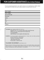
...your Authorized Parts Distributor) ACCESSORIES ADDITIONAL CUSTOMER INFORMATION TO WRITE: For service problems, warranty information, missing items and other assistance: Sharp Electronics Corporation Customer Assistance Center 1300 Naperville Drive Romeoville, IL 60446-1091 TO ACCESS THE INTERNET: www.sharpusa.com Please provide the... write or call: model number, serial number, date of purchase, your complete mailing address (including zip code), your nearest Sharp Authorized Servicer) PARTS (for reporting loss or theft, please record below the model and serial number located on the back side of...
...your Authorized Parts Distributor) ACCESSORIES ADDITIONAL CUSTOMER INFORMATION TO WRITE: For service problems, warranty information, missing items and other assistance: Sharp Electronics Corporation Customer Assistance Center 1300 Naperville Drive Romeoville, IL 60446-1091 TO ACCESS THE INTERNET: www.sharpusa.com Please provide the... write or call: model number, serial number, date of purchase, your complete mailing address (including zip code), your nearest Sharp Authorized Servicer) PARTS (for reporting loss or theft, please record below the model and serial number located on the back side of...
CV-P09LX , CV-P10LC , CV-P10MX , CV-P12LX Operation Manual
Page 5
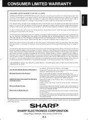
... FITNESS FOR USE ARE LIMITED TO THE PERIOD(S) FROM THE DATE OF PURCHASE SET FORTH BELOW. Correction of Sharp to Obtain Service: CV-P09LX, CV-P12LX, CV-P10LC or CV-P10MX Portable Air Conditioner. THIS WARRANTY GIVES YOU SPECIFlC LEGAL RIGHTS. Your Product Model Number & Description: Warranty Period for... incidental or consequential damages, so the above limitation may not apply to improper voltage or other than an authorized servicer. From a Sharp Authorized Servicer located in its original container, will , at its option, either repair the defect or replace the defective Product or ...
... FITNESS FOR USE ARE LIMITED TO THE PERIOD(S) FROM THE DATE OF PURCHASE SET FORTH BELOW. Correction of Sharp to Obtain Service: CV-P09LX, CV-P12LX, CV-P10LC or CV-P10MX Portable Air Conditioner. THIS WARRANTY GIVES YOU SPECIFlC LEGAL RIGHTS. Your Product Model Number & Description: Warranty Period for... incidental or consequential damages, so the above limitation may not apply to improper voltage or other than an authorized servicer. From a Sharp Authorized Servicer located in its original container, will , at its option, either repair the defect or replace the defective Product or ...
CV-P09LX , CV-P10LC , CV-P10MX , CV-P12LX Operation Manual
Page 6
...DATE OF PURCHASE Dealer Name Address City Province Postal Code Telephone TO PHONE: Dial 1-905-568-7140 for: SERVICE (for your nearest Sharp Authorized Servicer) PARTS (for reporting loss or theft, please record below the model and serial number located on the back side of the unit.... (including area code) and description of the problem. Customer Care 335 Britannia Road East Mississauga, Ontario L4Z 1W9 TO ACCESS THE INTERNET: www.sharp.ca Please provide the following information when you call : model number, serial number, date of purchase, your complete mailing address (including Postal Code...
...DATE OF PURCHASE Dealer Name Address City Province Postal Code Telephone TO PHONE: Dial 1-905-568-7140 for: SERVICE (for your nearest Sharp Authorized Servicer) PARTS (for reporting loss or theft, please record below the model and serial number located on the back side of the unit.... (including area code) and description of the problem. Customer Care 335 Britannia Road East Mississauga, Ontario L4Z 1W9 TO ACCESS THE INTERNET: www.sharp.ca Please provide the following information when you call : model number, serial number, date of purchase, your complete mailing address (including Postal Code...
CV-P09LX , CV-P10LC , CV-P10MX , CV-P12LX Operation Manual
Page 7
... result of abusive operation, negligence, accident, improper installation or inappropriate use as outlined in the owner's manual. (b) Any Sharp product tampered with, modified, adjusted or repaired by any party other dealer, service centre or their agent or employee is ... on contract, negligence, strict liability or otherwise. Sharp Electronics of information. The purchaser will be found in material and workmanship. WARRANTY PERIODS: Audio Products Camcorder DVD Products Projector LCD TV Microwave Oven Air Purifier Portable Air Conditioner Parts & Labour (exceptions noted) 1...
... result of abusive operation, negligence, accident, improper installation or inappropriate use as outlined in the owner's manual. (b) Any Sharp product tampered with, modified, adjusted or repaired by any party other dealer, service centre or their agent or employee is ... on contract, negligence, strict liability or otherwise. Sharp Electronics of information. The purchaser will be found in material and workmanship. WARRANTY PERIODS: Audio Products Camcorder DVD Products Projector LCD TV Microwave Oven Air Purifier Portable Air Conditioner Parts & Labour (exceptions noted) 1...
CV-P09LX , CV-P10LC , CV-P10MX , CV-P12LX Operation Manual
Page 8
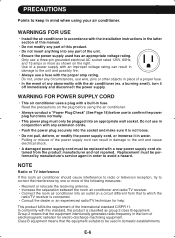
Read the precautions on the plug before using your air conditioner. Do not use wire, pins or other objects in place of a proper fuse. • In the event of any circumstances, use in conjunction with this standard, this product is classified as shown on a circuit different from the product manufacturer and not repaired. Use of the power supply cord can result in damage to the unit and possibly fire. • Always use a three-pin grounded electrical AC socket rated 125V, 60Hz, and 15 amps or more of the following measures: • Reorient or relocate the receiving antenna. ...
Read the precautions on the plug before using your air conditioner. Do not use wire, pins or other objects in place of a proper fuse. • In the event of any circumstances, use in conjunction with this standard, this product is classified as shown on a circuit different from the product manufacturer and not repaired. Use of the power supply cord can result in damage to the unit and possibly fire. • Always use a three-pin grounded electrical AC socket rated 125V, 60Hz, and 15 amps or more of the following measures: • Reorient or relocate the receiving antenna. ...

CV-P09LX , CV-P10LC , CV-P10MX , CV-P12LX Operation Manual
Page 9
ENGLISH WARNING ABOUT GROUNDING • Improper use , especially if using gas appliances. • Be sure to turn the unit off and disconnect the power supply cord before performing any maintenance or cleaning. • Do not splash or pour water directly onto the unit. In the event of an electrical short circuit, grounding reduces the risk of electric shock. The drained water may be reduced or stop completely. Cooling performance may spill out into the room. • The temperature around the drainage hose must be below freezing point when used , make sure the electrical box is ...
ENGLISH WARNING ABOUT GROUNDING • Improper use , especially if using gas appliances. • Be sure to turn the unit off and disconnect the power supply cord before performing any maintenance or cleaning. • Do not splash or pour water directly onto the unit. In the event of an electrical short circuit, grounding reduces the risk of electric shock. The drained water may be reduced or stop completely. Cooling performance may spill out into the room. • The temperature around the drainage hose must be below freezing point when used , make sure the electrical box is ...
CV-P09LX , CV-P10LC , CV-P10MX , CV-P12LX Operation Manual
Page 10
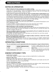
After power is set close to 64°F in the unit may occur when the unit is reinstated, restart the air conditioner. Any previous settings will be operated within three minutes, a protective device in low ambient temperature conditions, especially at least three minutes before restarting the unit. The unit generates heat during use . • Turn off for safety. • In the event of air as that blown out will be sure to keep out direct sunlight while in cool mode. In this is home. See page 30 on how to drain out water within the unit. (See page 29) OPERATING ...
After power is set close to 64°F in the unit may occur when the unit is reinstated, restart the air conditioner. Any previous settings will be operated within three minutes, a protective device in low ambient temperature conditions, especially at least three minutes before restarting the unit. The unit generates heat during use . • Turn off for safety. • In the event of air as that blown out will be sure to keep out direct sunlight while in cool mode. In this is home. See page 30 on how to drain out water within the unit. (See page 29) OPERATING ...
CV-P09LX , CV-P10LC , CV-P10MX , CV-P12LX Operation Manual
Page 11
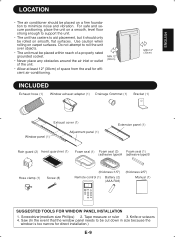
Use caution when rolling on a firm foundation to roll the unit over objects. • The unit must be placed within reach of a properly rated grounded socket. • Never place any obstacles around the air inlet or outlet of the unit. • Allow at least 12" (30cm) of space from the wall for direct installation.) E-9 Screwdriver(medium size Phillips) 2. MIN.12" (30cm) MIN.12" (30cm) INCLUDED Exhaust hose (1) Window exhaust adapter (1) Drainage Grommet (1) Bracket (1) Exhaust cover (1) Window panel (1) Adjustment panel (1) Extension panel (1) Rain guard (2) Insect guard ...
Use caution when rolling on a firm foundation to roll the unit over objects. • The unit must be placed within reach of a properly rated grounded socket. • Never place any obstacles around the air inlet or outlet of the unit. • Allow at least 12" (30cm) of space from the wall for direct installation.) E-9 Screwdriver(medium size Phillips) 2. MIN.12" (30cm) MIN.12" (30cm) INCLUDED Exhaust hose (1) Window exhaust adapter (1) Drainage Grommet (1) Bracket (1) Exhaust cover (1) Window panel (1) Adjustment panel (1) Extension panel (1) Rain guard (2) Insect guard ...

CV-P09LX , CV-P10LC , CV-P10MX , CV-P12LX Operation Manual
Page 12
PART NAMES FRONT VIEW 1 1 Air Outlet 2 2 Vertical louvers 3 3 Horizontal louvers 4 4 PLASMACLUSTER Lamp (blue) 5 5 Remote control signal receiver 6 window 7 6 POWER Button 8 7 OPERATION Lamp (red) 9 0 8 TIMER Lamp (orange) 0 9 MEGA COOL Lamp (green) 0 0 Air inlet REAR VIEW q q Exhaust air outlet w w Window exhaust adapter e e Exhaust hose r r Remote control hook t t Air filters y u y Drainage nozzle and stopcock u Power supply cord hooks i Drainpipe nozzle and stopcock i o Power supply cord o p Power plug p a a Casters(4) NOTE: Actual unit might ...
PART NAMES FRONT VIEW 1 1 Air Outlet 2 2 Vertical louvers 3 3 Horizontal louvers 4 4 PLASMACLUSTER Lamp (blue) 5 5 Remote control signal receiver 6 window 7 6 POWER Button 8 7 OPERATION Lamp (red) 9 0 8 TIMER Lamp (orange) 0 9 MEGA COOL Lamp (green) 0 0 Air inlet REAR VIEW q q Exhaust air outlet w w Window exhaust adapter e e Exhaust hose r r Remote control hook t t Air filters y u y Drainage nozzle and stopcock u Power supply cord hooks i Drainpipe nozzle and stopcock i o Power supply cord o p Power plug p a a Casters(4) NOTE: Actual unit might ...
CV-P09LX , CV-P10LC , CV-P10MX , CV-P12LX Operation Manual
Page 13
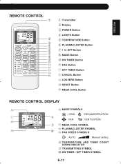
ENGLISH REMOTE CONTROL 1 2 3 4 5 6 7 8 9 0 q w e r t 1 Transmitter 2 Display 3 POWER Button 4 LIGHTS Button 5 TEMPERATURE Button 6 PLASMACLUSTER Button 7 1 hr OFF Button 8 MODE Button 9 ON TIMER Button 0 FAN Button q OFF TIMER Button w CANCEL Button e LOUVERS Button r RESET Button t MEGA COOL Button REMOTE CONTROL DISPLAY y y MODE SYMBOLS : COOL : DEHUMIDIFICATION u p : FAN : VENTILATION i a u MEGA COOL SYMBOL i PLASMACLUSTER SYMBOL o s o FAN SPEED SYMBOLS : AUTO : Manual setting p TEMPERATURE AND TIMER COUNT DOWN INDICATOR a TRANSMITTING SYMBOL s ON TIMER / OFF TIMER SYMBOL...
ENGLISH REMOTE CONTROL 1 2 3 4 5 6 7 8 9 0 q w e r t 1 Transmitter 2 Display 3 POWER Button 4 LIGHTS Button 5 TEMPERATURE Button 6 PLASMACLUSTER Button 7 1 hr OFF Button 8 MODE Button 9 ON TIMER Button 0 FAN Button q OFF TIMER Button w CANCEL Button e LOUVERS Button r RESET Button t MEGA COOL Button REMOTE CONTROL DISPLAY y y MODE SYMBOLS : COOL : DEHUMIDIFICATION u p : FAN : VENTILATION i a u MEGA COOL SYMBOL i PLASMACLUSTER SYMBOL o s o FAN SPEED SYMBOLS : AUTO : Manual setting p TEMPERATURE AND TIMER COUNT DOWN INDICATOR a TRANSMITTING SYMBOL s ON TIMER / OFF TIMER SYMBOL...

CV-P09LX , CV-P10LC , CV-P10MX , CV-P12LX Operation Manual
Page 14
"A" Side "A" will now be unable to shut the exhaust cover. (1) Remove the adjustment panel from the window panel, and cut the window panel to ensure that its four projections fit into the holes in the insect guard net. Foam seal A (adhesive type) 4 Attach the window panel to the window stool with 2 screws. 22"~ 24" Exhaust cover Cut Adjustment panel Window panel Window stool E-12 The window panel cannot be installed in windows less than 22" (559mm) wide, as you will now be uppermost, as indicated in the diagram. Window panel (2) Open the window sash and place the window panel ...
"A" Side "A" will now be unable to shut the exhaust cover. (1) Remove the adjustment panel from the window panel, and cut the window panel to ensure that its four projections fit into the holes in the insect guard net. Foam seal A (adhesive type) 4 Attach the window panel to the window stool with 2 screws. 22"~ 24" Exhaust cover Cut Adjustment panel Window panel Window stool E-12 The window panel cannot be installed in windows less than 22" (559mm) wide, as you will now be uppermost, as indicated in the diagram. Window panel (2) Open the window sash and place the window panel ...

CV-P09LX , CV-P10LC , CV-P10MX , CV-P12LX Operation Manual
Page 15
Foam seal A (adhesive type) Foam seal B (adhesive type) 7 Cut the foam seal to the stool with 3 screws. ENGLISH If the inner width of the window is between 24" (609mm) and 36.8" (934mm) inclusive. (1) Open the window sash and place the window panel on the window stool. (2) Slide the adjustment panel to fit the window frame width. (3) Secure the window panel to an appropriate length and seal the opening between the top of the window is between 36.8" (934mm) and 48" (1219mm) inclusive. (1) Attach the extension panel to the adjustment panel. (2) Open the window sash and place the ...
Foam seal A (adhesive type) Foam seal B (adhesive type) 7 Cut the foam seal to the stool with 3 screws. ENGLISH If the inner width of the window is between 24" (609mm) and 36.8" (934mm) inclusive. (1) Open the window sash and place the window panel on the window stool. (2) Slide the adjustment panel to fit the window frame width. (3) Secure the window panel to an appropriate length and seal the opening between the top of the window is between 36.8" (934mm) and 48" (1219mm) inclusive. (1) Attach the extension panel to the adjustment panel. (2) Open the window sash and place the ...

CV-P09LX , CV-P10LC , CV-P10MX , CV-P12LX Operation Manual
Page 16
Insect guard net Hole Projection "A" Rain guard 2 Attach the guard combined above to the same height as indicated in the window panel. The window panel cannot be installed in windows less than 22" (559mm) high, as you will be uppermost, as indicated in the window. Foam seal A (adhesive type) Window panel Exhaust cover Cut Adjustment panel Window panel 22"~24" E-14 Projection Window panel "A" 3 Cut the foam seal A (adhesive type) to the proper length and attach it is between 22" (559mm) and 24" (609mm) inclusive. Side "A" will now be at the top, as the window. (2) ...
Insect guard net Hole Projection "A" Rain guard 2 Attach the guard combined above to the same height as indicated in the window panel. The window panel cannot be installed in windows less than 22" (559mm) high, as you will be uppermost, as indicated in the window. Foam seal A (adhesive type) Window panel Exhaust cover Cut Adjustment panel Window panel 22"~24" E-14 Projection Window panel "A" 3 Cut the foam seal A (adhesive type) to the proper length and attach it is between 22" (559mm) and 24" (609mm) inclusive. Side "A" will now be at the top, as the window. (2) ...

CV-P09LX , CV-P10LC , CV-P10MX , CV-P12LX Operation Manual
Page 17
Adjustment panel Extension panel 24"~36.8" 36.8"~48" 5 Cut the foam seals (adhesive type) A and B to the proper length and attach them to the window panel. Attach foam seal A to the window panel and extension panel, and attach foam seal B to the adjustment panel. 6 Close the window sash securely against the Window panel. 7 Cut the foam seal to an appropriate length and seal the opening between the side of the window is between 36.8" (934mm) and 48" (1219mm) inclusive. (1) Attach the extension panel to the adjustment panel. (2) Open the window sash and place the window panel on the ...
Adjustment panel Extension panel 24"~36.8" 36.8"~48" 5 Cut the foam seals (adhesive type) A and B to the proper length and attach them to the window panel. Attach foam seal A to the window panel and extension panel, and attach foam seal B to the adjustment panel. 6 Close the window sash securely against the Window panel. 7 Cut the foam seal to an appropriate length and seal the opening between the side of the window is between 36.8" (934mm) and 48" (1219mm) inclusive. (1) Attach the extension panel to the adjustment panel. (2) Open the window sash and place the window panel on the ...

CV-P09LX , CV-P10LC , CV-P10MX , CV-P12LX Operation Manual
Page 18
three times) until it is installed in a double-hung sash window. Window exhaust adapter Extend Exhaust hose Projection Hole "TOP" The exhaust hose should be at the top when it is installed in a sliding sash window. Insert the two projections on the exhaust hose adapter into the window exhaust adapter, and turn it must be twisted or bent. Surface of window exhaust adapter marked "TOP" should be on the window panel, and attach the window exhaust adapter. Make sure they are securely attached afterwards. 2 Attach the exhaust hose adapter to the exhaust hose. however, it (...
three times) until it is installed in a double-hung sash window. Window exhaust adapter Extend Exhaust hose Projection Hole "TOP" The exhaust hose should be at the top when it is installed in a sliding sash window. Insert the two projections on the exhaust hose adapter into the window exhaust adapter, and turn it must be twisted or bent. Surface of window exhaust adapter marked "TOP" should be on the window panel, and attach the window exhaust adapter. Make sure they are securely attached afterwards. 2 Attach the exhaust hose adapter to the exhaust hose. however, it (...

CV-P09LX , CV-P10LC , CV-P10MX , CV-P12LX Operation Manual
Page 19
"PUSH" Projection E-17 ENGLISH Removal of the exhaust hose 1 Remove the window exhaust adapter. Pull out and remove the window exhaust adapter by pushing down two "PUSH" markings, and slide and close the exhaust cover in the window panel. 2 Remove the exhaust hose adapter from the unit by pushing down on the two projections. Lift up and remove the exhaust hose adapter from the unit.
"PUSH" Projection E-17 ENGLISH Removal of the exhaust hose 1 Remove the window exhaust adapter. Pull out and remove the window exhaust adapter by pushing down two "PUSH" markings, and slide and close the exhaust cover in the window panel. 2 Remove the exhaust hose adapter from the unit by pushing down on the two projections. Lift up and remove the exhaust hose adapter from the unit.
CV-P09LX , CV-P10LC , CV-P10MX , CV-P12LX Operation Manual
Page 20
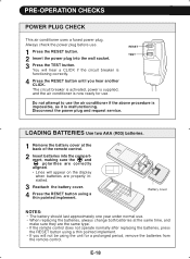
The circuit breaker is activated, power is supplied, and the air conditioner is now ready for a prolonged period, remove the batteries from the remote control. polarities are correctly aligned. • Lines will appear on the display when batteries are the same type. • If the remote control does not operate normally after replacing the batteries, press the RESET button using a thin pointed implement. Disconnect the power plug and request service. E-18 RESET TEST Do not attempt to use the air conditioner if the above procedure is impossible, as it is functioning correctly. 4 ...
The circuit breaker is activated, power is supplied, and the air conditioner is now ready for a prolonged period, remove the batteries from the remote control. polarities are correctly aligned. • Lines will appear on the display when batteries are the same type. • If the remote control does not operate normally after replacing the batteries, press the RESET button using a thin pointed implement. Disconnect the power plug and request service. E-18 RESET TEST Do not attempt to use the air conditioner if the above procedure is impossible, as it is functioning correctly. 4 ...

CV-P09LX , CV-P10LC , CV-P10MX , CV-P12LX Operation Manual
Page 21
tect the remote control from the unit, lift the remote control up to direct sunlight or near a heater. Remote control hook E-19 Pro- When attached, to remove the remote control from moisture and shock which can discolor or damage it out. ENGLISH HOW TO USE THE REMOTE CONTROL Point the remote control towards the units signal receiver window and press the desired button. To prevent the remote control from other remote controllers for televisions, VCRs or other equipment used in use. CAUTION • Do not expose the signal receiver window to block out the sunlight. &#...
tect the remote control from the unit, lift the remote control up to direct sunlight or near a heater. Remote control hook E-19 Pro- When attached, to remove the remote control from moisture and shock which can discolor or damage it out. ENGLISH HOW TO USE THE REMOTE CONTROL Point the remote control towards the units signal receiver window and press the desired button. To prevent the remote control from other remote controllers for televisions, VCRs or other equipment used in use. CAUTION • Do not expose the signal receiver window to block out the sunlight. &#...

CV-P09LX , CV-P10LC , CV-P10MX , CV-P12LX Operation Manual
Page 22
Stopcock 1 Press the MODE button to set within the range 3 of 64°F to 86°F. 1 4 4 Press the FAN button to select COOL mode. COOL DEHUM FAN VENT 32 Press the POWER button to start operation. • The red OPERATION lamp on the unit will light. 2 3 Press the TEMPERATURE button to set the desired temperature. • The temperature can be set the de- AUTO QUIET LOW HIGH TO TURN OFF Press the POWER button again. • The red OPERATION lamp on the unit will turn the drainage nozzle to the CLOSE position, Drainage nozzle and check the drainage nozzle...
Stopcock 1 Press the MODE button to set within the range 3 of 64°F to 86°F. 1 4 4 Press the FAN button to select COOL mode. COOL DEHUM FAN VENT 32 Press the POWER button to start operation. • The red OPERATION lamp on the unit will light. 2 3 Press the TEMPERATURE button to set the desired temperature. • The temperature can be set the de- AUTO QUIET LOW HIGH TO TURN OFF Press the POWER button again. • The red OPERATION lamp on the unit will turn the drainage nozzle to the CLOSE position, Drainage nozzle and check the drainage nozzle...