CV-10NH Operation Manual
Page 3
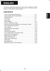
... WINDOW PANEL E-10 • INSTALLATION AND REMOVAL OF EXHAUST HOSE .........E-14 • PRE-OPERATION CHECKS E-16 • COOL MODE E-18 • DEHUMIDIFICATION MODE E-19 • FAN MODE E-20 • VENTILATION MODE E-20 • TO CHANGE AIR FLOW DIRECTION ...E-21 • MEGA COOL OPERATION E-22 • ONE-HOUR OFF TIMER E-22 • TIMER OPERATION E-23 • MAIN UNIT OPERATION E-25 • DRAINAGE E-26 • MAINTENANCE E-27 • BEFORE CALLING FOR SERVICE E-28 E-1 ENGLISH ENGLISH This manual explains the proper use of your new air conditioner...
... WINDOW PANEL E-10 • INSTALLATION AND REMOVAL OF EXHAUST HOSE .........E-14 • PRE-OPERATION CHECKS E-16 • COOL MODE E-18 • DEHUMIDIFICATION MODE E-19 • FAN MODE E-20 • VENTILATION MODE E-20 • TO CHANGE AIR FLOW DIRECTION ...E-21 • MEGA COOL OPERATION E-22 • ONE-HOUR OFF TIMER E-22 • TIMER OPERATION E-23 • MAIN UNIT OPERATION E-25 • DRAINAGE E-26 • MAINTENANCE E-27 • BEFORE CALLING FOR SERVICE E-28 E-1 ENGLISH ENGLISH This manual explains the proper use of your new air conditioner...
CV-10NH Operation Manual
Page 6
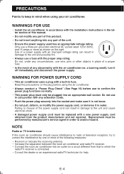
...; Always conduct a "Power Plug Check" (See Page 16) before using your air conditioner. Pulling or misuse of the power supply cord can result in the latter section of this manual. • Do not modify any part of this room air conditioner should cause interference to radio or television reception, try to correct the interference by...
...; Always conduct a "Power Plug Check" (See Page 16) before using your air conditioner. Pulling or misuse of the power supply cord can result in the latter section of this manual. • Do not modify any part of this room air conditioner should cause interference to radio or television reception, try to correct the interference by...

CV-10NH Operation Manual
Page 11
ENGLISH REMOTE CONTROL 1 2 3 4 5 6 7 8 9 0 q w e 1 Transmitter 2 Display 3 POWER Button 4 TEMPERATURE Button 5 1 hr OFF Button 6 MODE Button 7 ON TIMER Button 8 FAN Button 9 OFF TIMER Button 0 CANCEL Button q LOUVERS Button w RESET Button e MEGA COOL Button REMOTE CONTROL DISPLAY r r MODE SYMBOLS : COOL : DEHUMIDIFICATION t u : FAN : VENTILATION i t MEGA COOL SYMBOL y FAN SPEED SYMBOLS y o : AUTO Quiet : Manual setting Low High u TEMPERATURE AND TIMER COUNT DOWN INDICATOR i TRANSMITTING SYMBOL o ON TIMER / OFF TIMER SYMBOL E-9
ENGLISH REMOTE CONTROL 1 2 3 4 5 6 7 8 9 0 q w e 1 Transmitter 2 Display 3 POWER Button 4 TEMPERATURE Button 5 1 hr OFF Button 6 MODE Button 7 ON TIMER Button 8 FAN Button 9 OFF TIMER Button 0 CANCEL Button q LOUVERS Button w RESET Button e MEGA COOL Button REMOTE CONTROL DISPLAY r r MODE SYMBOLS : COOL : DEHUMIDIFICATION t u : FAN : VENTILATION i t MEGA COOL SYMBOL y FAN SPEED SYMBOLS y o : AUTO Quiet : Manual setting Low High u TEMPERATURE AND TIMER COUNT DOWN INDICATOR i TRANSMITTING SYMBOL o ON TIMER / OFF TIMER SYMBOL E-9

CV-10NH Operation Manual
Page 23
... when operated the next time. E-21 ENGLISH TO CHANGE AIR FLOW DIRECTION UP / DOWN AIR FLOW DIRECTION 1 Press the LOUVERS button on the louvers. Vertical louvers CAUTION Never attempt to adjust the horizontal louvers manually. • Manual adjustment of the horizontal louvers can cause the unit to... the extreme left or right in the COOL or DEHUMIDIFI- Horizontal louvers LEFT / RIGHT AIR FLOW DIRECTION Hold the vertical louver as shown in ...
... when operated the next time. E-21 ENGLISH TO CHANGE AIR FLOW DIRECTION UP / DOWN AIR FLOW DIRECTION 1 Press the LOUVERS button on the louvers. Vertical louvers CAUTION Never attempt to adjust the horizontal louvers manually. • Manual adjustment of the horizontal louvers can cause the unit to... the extreme left or right in the COOL or DEHUMIDIFI- Horizontal louvers LEFT / RIGHT AIR FLOW DIRECTION Hold the vertical louver as shown in ...


