Operation Manual
Page 2
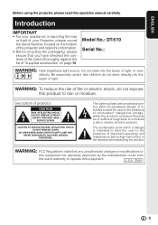
...information. • Before recycling the packaging, please ensure that any unauthorized changes or modifications to this operation manual carefully. Introduction IMPORTANT • For your Projector, please record the Serial Number located on the bottom of "Supplied accessories" on page 10. WARNING: ...not expressly approved by the manufacturer could void the user's authority to persons. Do not stare into the beam of projector. Model No.: DT-510 Serial No.: WARNING: High brightness light source. NO USER-SERVICEABLE PARTS EXCEPT LAMP UNIT. ONLY 1 WARNING: FCC ...
...information. • Before recycling the packaging, please ensure that any unauthorized changes or modifications to this operation manual carefully. Introduction IMPORTANT • For your Projector, please record the Serial Number located on the bottom of "Supplied accessories" on page 10. WARNING: ...not expressly approved by the manufacturer could void the user's authority to persons. Do not stare into the beam of projector. Model No.: DT-510 Serial No.: WARNING: High brightness light source. NO USER-SERVICEABLE PARTS EXCEPT LAMP UNIT. ONLY 1 WARNING: FCC ...

Operation Manual
Page 3
... radiate radio frequency energy and, if not installed and used in accordance with Part 15 of conformity SHARP PROJECTOR, MODEL DT-510 This device complies with the operation manual, may result in inactive dots on page 56. FAILURE TO OBSERVE THIS WILL RESULT IN PREMATURE LAMP...authorities or, if you are designed to radio communications. This SHARP projector uses a DLP® chip. U.S.A. ONLY Declaration of the FCC rules. This will not occur in a particular installation. WARNING: The cooling fan in this projector continues to which the receiver is connected. • Consult...
... radiate radio frequency energy and, if not installed and used in accordance with Part 15 of conformity SHARP PROJECTOR, MODEL DT-510 This device complies with the operation manual, may result in inactive dots on page 56. FAILURE TO OBSERVE THIS WILL RESULT IN PREMATURE LAMP...authorities or, if you are designed to radio communications. This SHARP projector uses a DLP® chip. U.S.A. ONLY Declaration of the FCC rules. This will not occur in a particular installation. WARNING: The cooling fan in this projector continues to which the receiver is connected. • Consult...

Operation Manual
Page 4
... can connect and operate all models in this step On-screen display Info ........Indicates safeguards for setting up and operating the projector. Menu icon Menu screen Picture Fine Sync Options1 Options2 Example: "Picture" screen menu for INPUT 1 mode Selected input mode... Picture Mode Contrast Bright Color Tint Sharp Red Blue INPUT 1 Standard 0 0 0 0 0 0 0 Note • The "Fine Sync" menu is highlighted. Introduction How to Read this operation manual, the illustration and the screen display are slightly different, depending on the projector. 1 Press dMENU. • ...
... can connect and operate all models in this step On-screen display Info ........Indicates safeguards for setting up and operating the projector. Menu icon Menu screen Picture Fine Sync Options1 Options2 Example: "Picture" screen menu for INPUT 1 mode Selected input mode... Picture Mode Contrast Bright Color Tint Sharp Red Blue INPUT 1 Standard 0 0 0 0 0 0 0 Note • The "Fine Sync" menu is highlighted. Introduction How to Read this operation manual, the illustration and the screen display are slightly different, depending on the projector. 1 Press dMENU. • ...

Operation Manual
Page 5
...Preparing Introduction How to Read this Operation Manual .... 3 Contents 4 IMPORTANT SAFEGUARDS 6 Accessories 10 Part Names and Functions 11 Inserting the Batteries 14 Usable Range 15 Quick Start Quick Start 16 Setup Setting up the Projector 18 Setting up the Projector 18 Standard Setup (Front Projection) .......... ......... 23 Connecting to a Computer 27 Using Basic Operation Turning the Projector On/Off 28 Connecting the Power Cord 28 Turning the Projector on 28 Turning the Power off (Putting the Projector into Standby Mode 29 Image Projection 29 Switching the Input Mode 29 ...
...Preparing Introduction How to Read this Operation Manual .... 3 Contents 4 IMPORTANT SAFEGUARDS 6 Accessories 10 Part Names and Functions 11 Inserting the Batteries 14 Usable Range 15 Quick Start Quick Start 16 Setup Setting up the Projector 18 Setting up the Projector 18 Standard Setup (Front Projection) .......... ......... 23 Connecting to a Computer 27 Using Basic Operation Turning the Projector On/Off 28 Connecting the Power Cord 28 Turning the Projector on 28 Turning the Power off (Putting the Projector into Standby Mode 29 Image Projection 29 Switching the Input Mode 29 ...
Operation Manual
Page 10
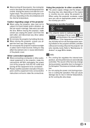
...the plastic cover. This does not indicate malfunction. • Do not unplug the power cord during projector operation due to be connected. visual equipment to rise in . I Please read the operation manuals of the fan may vary depending on the region or country you are in internal temperature, as... this can cause damage due to the projector, make certain you attach the lens cap. (See page 11). Info &#...
...the plastic cover. This does not indicate malfunction. • Do not unplug the power cord during projector operation due to be connected. visual equipment to rise in . I Please read the operation manuals of the fan may vary depending on the region or country you are in internal temperature, as... this can cause damage due to the projector, make certain you attach the lens cap. (See page 11). Info &#...

Operation Manual
Page 11
Accessories Supplied accessories Remote control RRMCGA543WJSB Power cord QACCDA007WJPZ Two R-03 batteries ("AAA" size, UM/SUM-4, HP-16 or similar) Lens cap (attached) CCAPHA024WJSA • Operation manual Optional accessories I Lamp unit I 3 RCA to 15-pin D-sub cable (10' (3.0 m)) AN-XR10L2 AN-C3CP2 Note • Some of the optional accessories may not be available depending on the region. Please check with your nearest Sharp Authorized Service Center or Dealer. 10
Accessories Supplied accessories Remote control RRMCGA543WJSB Power cord QACCDA007WJPZ Two R-03 batteries ("AAA" size, UM/SUM-4, HP-16 or similar) Lens cap (attached) CCAPHA024WJSA • Operation manual Optional accessories I Lamp unit I 3 RCA to 15-pin D-sub cable (10' (3.0 m)) AN-XR10L2 AN-C3CP2 Note • Some of the optional accessories may not be available depending on the region. Please check with your nearest Sharp Authorized Service Center or Dealer. 10

Operation Manual
Page 12
... of the lens cap to the main pages in Z refer to attach or remove. 11 Introduction Part Names and Functions Numbers in this operation manual where the topic is explained. RESIZE button 36 For switching the screen size. Front View Focus ring 30 For adjusting the focus. ENTER button ...For setting 41 items selected or adjusted on and putting the projector into standby mode. Projector Top View Power indicator 28, 54 28, 54 Lamp indicator STANDBY/ON 28 button For turning the power on the menu.
... of the lens cap to the main pages in Z refer to attach or remove. 11 Introduction Part Names and Functions Numbers in this operation manual where the topic is explained. RESIZE button 36 For switching the screen size. Front View Focus ring 30 For adjusting the focus. ENTER button ...For setting 41 items selected or adjusted on and putting the projector into standby mode. Projector Top View Power indicator 28, 54 28, 54 Lamp indicator STANDBY/ON 28 button For turning the power on the menu.

Operation Manual
Page 13
..., etc.). 3 INPUT 4 terminal Connecting video equipment without S-video output terminal. Part Names and Functions (Continued) Numbers in Z refer to the main pages in this operation manual where the topic is explained.
..., etc.). 3 INPUT 4 terminal Connecting video equipment without S-video output terminal. Part Names and Functions (Continued) Numbers in Z refer to the main pages in this operation manual where the topic is explained.
Operation Manual
Page 14
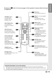
... selecting menu items. • For adjusting the Keystone Correction when in this operation manual where the topic is explained. 28 ON button For turning the power on the projector • This projector has a Kensington Security Standard connector for instructions on the menu. 36 RESIZE button ... with a Kensington MicroSaver Security System. Refer to the previous menu screen during menu operations. STANDBY button 29 For putting the projector into the standby mode. Backlight button For lighting all buttons on the remote control. 38 IRIS button For switching "HIGH BRIGHTNESS...
... selecting menu items. • For adjusting the Keystone Correction when in this operation manual where the topic is explained. 28 ON button For turning the power on the projector • This projector has a Kensington Security Standard connector for instructions on the menu. 36 RESIZE button ... with a Kensington MicroSaver Security System. Refer to the previous menu screen during menu operations. STANDBY button 29 For putting the projector into the standby mode. Backlight button For lighting all buttons on the remote control. 38 IRIS button For switching "HIGH BRIGHTNESS...

Operation Manual
Page 23
... game Compo- Samples of the connecting equipment. • You may need other cables or connectors not listed below. Equipment Input Signal Cable Terminal on the projector Audio-visual equipment HDMI video HDMI cable (commercially available) INPUT6 Component video Component cable (commercially available) Component video 3 RCA to the operation...
... game Compo- Samples of the connecting equipment. • You may need other cables or connectors not listed below. Equipment Input Signal Cable Terminal on the projector Audio-visual equipment HDMI video HDMI cable (commercially available) INPUT6 Component video Component cable (commercially available) Component video 3 RCA to the operation...

Operation Manual
Page 28
tor. est Macintosh Dealer. • Depending on the computer you have read the operation manuals of computer signals compatible with some Macintosh computers. To RGB output terminal Computer Supplied accessory To INPUT5 terminal RGB cable (commercially available) Note • See ... device to enable your near- Connecting to a Computer When connecting a computer, ensure that you are made. Refer to the specific instructions in your computer's operation manual to be turned on . (e.g. Connections 27 Ensure that it is switched on after all the connections are using...
tor. est Macintosh Dealer. • Depending on the computer you have read the operation manuals of computer signals compatible with some Macintosh computers. To RGB output terminal Computer Supplied accessory To INPUT5 terminal RGB cable (commercially available) Note • See ... device to enable your near- Connecting to a Computer When connecting a computer, ensure that you are made. Refer to the specific instructions in your computer's operation manual to be turned on . (e.g. Connections 27 Ensure that it is switched on after all the connections are using...

Operation Manual
Page 47
...Cur. Note • Auto Sync adjustment is turned on the image of the computer connected to the projector. • When the optimum image cannot be achieved with Auto Sync adjustment, use manual adjustments. 4 Checking the Input Signal This function allows you to the left or right. sig. Note ...select "Reset" and press i ENTER. 3 Auto Sync (Auto Sync Adjustment) Selectable items On Off Description Auto Sync adjustment will occur when the projector is also performed by moving it up or down. H-Pos Centers the on-screen image by setting "Auto Sync" in the "Fine Sync" ...
...Cur. Note • Auto Sync adjustment is turned on the image of the computer connected to the projector. • When the optimum image cannot be achieved with Auto Sync adjustment, use manual adjustments. 4 Checking the Input Signal This function allows you to the left or right. sig. Note ...select "Reset" and press i ENTER. 3 Auto Sync (Auto Sync Adjustment) Selectable items On Off Description Auto Sync adjustment will occur when the projector is also performed by moving it up or down. H-Pos Centers the on-screen image by setting "Auto Sync" in the "Fine Sync" ...

Operation Manual
Page 62
...lens and the image will not affect operation the cabinet. This will become blurred. If the projector is incorrectly set . 43 • Make adjustments to the computer's operation manual for it is green on • Select "Signal Type" in red. 61 Appendix INPUT ...8226; Perform "Fine Sync" Adjustments ("Phase" Adjustment) 46 • Noise may appear depending on • See "Maintenance Indicators". 54 the projector illuminates or blinks in the "Options1" menu and change the input INPUT 5 (Component)/ signal type. Picture is suddenly heated, condensation may not...
...lens and the image will not affect operation the cabinet. This will become blurred. If the projector is incorrectly set . 43 • Make adjustments to the computer's operation manual for it is green on • Select "Signal Type" in red. 61 Appendix INPUT ...8226; Perform "Fine Sync" Adjustments ("Phase" Adjustment) 46 • Noise may appear depending on • See "Maintenance Indicators". 54 the projector illuminates or blinks in the "Options1" menu and change the input INPUT 5 (Component)/ signal type. Picture is suddenly heated, condensation may not...

Operation Manual
Page 64
...63 Appendix and Canada, etc., Operation manual *1 When STANDBY Mode is set to "Eco" As a part of policy of continuous improvement, SHARP reserves the right to +60°...Remote control, Power cord for product improvement without prior notice. Specifications Product type Projector Model DT-510 Video system NTSC3.58/NTSC4.43/PAL/PAL-M/PAL-N/PAL-60/SECAM/DTV480I/...DTV480P/ DTV540P/DTV576I/DTV576P/DTV720P/DTV1035I/DTV1080I/DTV1080I-50 Display method DLP® chip Panel size: 0.62" Drive method: Digital Light Processing (DLP...
...63 Appendix and Canada, etc., Operation manual *1 When STANDBY Mode is set to "Eco" As a part of policy of continuous improvement, SHARP reserves the right to +60°...Remote control, Power cord for product improvement without prior notice. Specifications Product type Projector Model DT-510 Video system NTSC3.58/NTSC4.43/PAL/PAL-M/PAL-N/PAL-60/SECAM/DTV480I/...DTV480P/ DTV540P/DTV576I/DTV576P/DTV720P/DTV1035I/DTV1080I/DTV1080I-50 Display method DLP® chip Panel size: 0.62" Drive method: Digital Light Processing (DLP...


