Operation Manual
Page 2
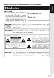
...electric shock, do not stare directly into the beam of projector. CAUTION RISK OF ELECTRIC SHOCK. U.S.A. DO NOT REMOVE SCREWS EXCEPT SPECIFIED USER SERVICE SCREW. REFER SERVICING TO QUALIFIED SERVICE PERSONNEL. Model No.: DT-510 Serial No.: WARNING: High brightness light source. NO USER...the product's enclosure that children do not expose this operation manual carefully. See bottom of light, or view directly. ONLY 1 Be especially careful that may be of "Supplied accessories" on the bottom of the projector and retain this information. • Before recycling the ...
...electric shock, do not stare directly into the beam of projector. CAUTION RISK OF ELECTRIC SHOCK. U.S.A. DO NOT REMOVE SCREWS EXCEPT SPECIFIED USER SERVICE SCREW. REFER SERVICING TO QUALIFIED SERVICE PERSONNEL. Model No.: DT-510 Serial No.: WARNING: High brightness light source. NO USER...the product's enclosure that children do not expose this operation manual carefully. See bottom of light, or view directly. ONLY 1 Be especially careful that may be of "Supplied accessories" on the bottom of the projector and retain this information. • Before recycling the ...

Operation Manual
Page 3
...there are designed to provide reasonable protection against harmful interference in a residential installation. As with the operation manual, may result in inactive dots on the remote control. This unit has some inactive pixels within acceptable ...DT-510 This device complies with the limits for a Class B digital device, pursuant to run for help. For disposal or recycling information, please contact your local authorities or, if you are located in the United States of mercury. If this projector continues to Part 15 of the FCC rules. This SHARP projector uses a DLP...
...there are designed to provide reasonable protection against harmful interference in a residential installation. As with the operation manual, may result in inactive dots on the remote control. This unit has some inactive pixels within acceptable ...DT-510 This device complies with the limits for a Class B digital device, pursuant to run for help. For disposal or recycling information, please contact your local authorities or, if you are located in the United States of mercury. If this projector continues to Part 15 of the FCC rules. This SHARP projector uses a DLP...

Operation Manual
Page 4
... PP. 61 and 62 Index P. 65 3 Buttons used in the same manner. • In this Operation Manual I The specifications are slightly different, depending on the projector. 1 Press dMENU. • The "Picture" menu screen for the selected input mode is displayed. 2 Press...the menu icon to Read this operation manual, the illustration and the screen display are simplified for INPUT 3 or INPUT 4. SEL./ADJ. Note .........Indicates additional information for INPUT 1 mode Selected input mode Menu icons Picture Picture Mode Contrast Bright Color Tint Sharp Red Blue INPUT 1 Standard 0 0...
... PP. 61 and 62 Index P. 65 3 Buttons used in the same manner. • In this Operation Manual I The specifications are slightly different, depending on the projector. 1 Press dMENU. • The "Picture" menu screen for the selected input mode is displayed. 2 Press...the menu icon to Read this operation manual, the illustration and the screen display are simplified for INPUT 3 or INPUT 4. SEL./ADJ. Note .........Indicates additional information for INPUT 1 mode Selected input mode Menu icons Picture Picture Mode Contrast Bright Color Tint Sharp Red Blue INPUT 1 Standard 0 0...

Operation Manual
Page 5
...Preparing Introduction How to Read this Operation Manual .... 3 Contents 4 IMPORTANT SAFEGUARDS 6 Accessories 10 Part Names and Functions 11 Inserting the Batteries 14 Usable Range 15 Quick Start Quick Start 16 Setup Setting up the Projector 18 Setting up the Projector 18 Standard Setup (Front Projection) .......... ......... 23 Connecting to a Computer 27 Using Basic Operation Turning the Projector On/Off 28 Connecting the Power Cord 28 Turning the Projector on 28 Turning the Power off (Putting the Projector into Standby Mode 29 Image Projection 29 Switching the Input Mode 29 ...
...Preparing Introduction How to Read this Operation Manual .... 3 Contents 4 IMPORTANT SAFEGUARDS 6 Accessories 10 Part Names and Functions 11 Inserting the Batteries 14 Usable Range 15 Quick Start Quick Start 16 Setup Setting up the Projector 18 Setting up the Projector 18 Standard Setup (Front Projection) .......... ......... 23 Connecting to a Computer 27 Using Basic Operation Turning the Projector On/Off 28 Connecting the Power Cord 28 Turning the Projector on 28 Turning the Power off (Putting the Projector into Standby Mode 29 Image Projection 29 Switching the Input Mode 29 ...
Operation Manual
Page 10
...indicator on page 54 for the country you use an appropriate power cord for details. Introduction I When turning off the projector, the cooling fan runs to decrease the internal temperature for instructions on how to make the connections. Other connected equipment I When ... to be connected for a while. I Please read the operation manuals of the projector I When connecting a computer or other cables connected to it to "Maintenance In- When using the projector overseas, make sure you are using the projector, take care not to subject it . Info • The ...
...indicator on page 54 for the country you use an appropriate power cord for details. Introduction I When turning off the projector, the cooling fan runs to decrease the internal temperature for instructions on how to make the connections. Other connected equipment I When ... to be connected for a while. I Please read the operation manuals of the projector I When connecting a computer or other cables connected to it to "Maintenance In- When using the projector overseas, make sure you are using the projector, take care not to subject it . Info • The ...

Operation Manual
Page 12
Introduction Part Names and Functions Numbers in this operation manual where the topic is explained. ENTER button For setting 41 items selected or adjusted on and putting the projector into standby mode. HEIGHT 30 ADJUST lever 54 Temperature warning indicator 29 INPUT buttons (P/R) For switching input mode 1, 2, 3, 4, 5 or...Remote control sensor (front) Push both sides of the lens cap to the main pages in Z refer to attach or remove. 11 Projector Top View Power indicator 28, 54 28, 54 Lamp indicator STANDBY/ON 28 button For turning the power on the menu. Front View...
Introduction Part Names and Functions Numbers in this operation manual where the topic is explained. ENTER button For setting 41 items selected or adjusted on and putting the projector into standby mode. HEIGHT 30 ADJUST lever 54 Temperature warning indicator 29 INPUT buttons (P/R) For switching input mode 1, 2, 3, 4, 5 or...Remote control sensor (front) Push both sides of the lens cap to the main pages in Z refer to attach or remove. 11 Projector Top View Power indicator 28, 54 28, 54 Lamp indicator STANDBY/ON 28 button For turning the power on the menu. Front View...
Operation Manual
Page 14
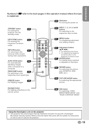
...setting screens. 41 Adjustment buttons (P/R/O/Q) • For selecting menu items. • For adjusting the Keystone Correction when in this operation manual where the topic is explained. 28 ON button For turning the power on how to use with a Kensington MicroSaver Security System. Backlight...size (STRETCH, SIDE BAR, etc.). 38 PICTURE MODE button For selecting the appropriate picture. STANDBY button 29 For putting the projector into the standby mode. AUTO SYNC button 46 For automatically adjusting images when connected to the previous menu screen during menu operations....
...setting screens. 41 Adjustment buttons (P/R/O/Q) • For selecting menu items. • For adjusting the Keystone Correction when in this operation manual where the topic is explained. 28 ON button For turning the power on how to use with a Kensington MicroSaver Security System. Backlight...size (STRETCH, SIDE BAR, etc.). 38 PICTURE MODE button For selecting the appropriate picture. STANDBY button 29 For putting the projector into the standby mode. AUTO SYNC button 46 For automatically adjusting images when connected to the previous menu screen during menu operations....

Operation Manual
Page 23
... available) Video INPUT4 Camera/ video game Cables for a camera or a video game Compo- Equipment Input Signal Cable Terminal on the projector Audio-visual equipment HDMI video HDMI cable (commercially available) INPUT6 Component video Component cable (commercially available) Component video 3 RCA to 15...camera or a video game INPUT3 S-video Cables for Connection • For more details of connection and cables, refer to the operation manual of the connecting equipment. • You may need other cables or connectors not listed below. Samples of Cables for a camera or...
... available) Video INPUT4 Camera/ video game Cables for a camera or a video game Compo- Equipment Input Signal Cable Terminal on the projector Audio-visual equipment HDMI video HDMI cable (commercially available) INPUT6 Component video Component cable (commercially available) Component video 3 RCA to 15...camera or a video game INPUT3 S-video Cables for Connection • For more details of connection and cables, refer to the operation manual of the connecting equipment. • You may need other cables or connectors not listed below. Samples of Cables for a camera or...

Operation Manual
Page 47
...Reset" and press i ENTER. 3 Auto Sync (Auto Sync Adjustment) Selectable items On Off Description Auto Sync adjustment will occur when the projector is also performed by setting "Auto Sync" in item 4. H-Pos Centers the on the currently selected input signal can automatically adjust the computer... image by pressing f AUTO SYNC on the remote control. • The Auto Sync adjustment may be achieved with Auto Sync adjustment, use manual adjustments. 4 Checking the Input Signal This function allows you to tracking on the remote control. • "Clock", "Phase", "H-Pos" and...
...Reset" and press i ENTER. 3 Auto Sync (Auto Sync Adjustment) Selectable items On Off Description Auto Sync adjustment will occur when the projector is also performed by setting "Auto Sync" in item 4. H-Pos Centers the on the currently selected input signal can automatically adjust the computer... image by pressing f AUTO SYNC on the remote control. • The Auto Sync adjustment may be achieved with Auto Sync adjustment, use manual adjustments. 4 Checking the Input Signal This function allows you to tracking on the remote control. • "Clock", "Phase", "H-Pos" and...

Operation Manual
Page 62
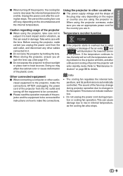
... • Power to the external connected devices is off. • The selected input mode is wrong. • Cables incorrectly connected to the projector. • Remote control battery has run out. • External output has not been set when connecting notebook computer. • The lamp unit...; If the picture is normal, the sound is blurred; occasionally heard from caused by room temperature changes. or performance. Refer to the computer's operation manual for it is to "Color", "Tint" and "BrilliantColor™" in "Picture Mode". (Video Input only) 48 • Video input system is...
... • Power to the external connected devices is off. • The selected input mode is wrong. • Cables incorrectly connected to the projector. • Remote control battery has run out. • External output has not been set when connecting notebook computer. • The lamp unit...; If the picture is normal, the sound is blurred; occasionally heard from caused by room temperature changes. or performance. Refer to the computer's operation manual for it is to "Color", "Tint" and "BrilliantColor™" in "Picture Mode". (Video Input only) 48 • Video input system is...

Operation Manual
Page 64
... some deviations from these values in individual units. 63 Appendix and Canada, etc., Operation manual *1 When STANDBY Mode is set to "Eco" As a part of policy of continuous improvement, SHARP reserves the right to +60°C) Cabinet Plastic I/R carrier frequency 38 kHz Dimensions ... product improvement without prior notice. SIGNAL: TTL level (positive/negative) VERTICAL SYNC. of production units. Specifications Product type Projector Model DT-510 Video system NTSC3.58/NTSC4.43/PAL/PAL-M/PAL-N/PAL-60/SECAM/DTV480I/DTV480P/ DTV540P/DTV576I/DTV576P/DTV720P/DTV1035I/DTV1080I/DTV1080I...
... some deviations from these values in individual units. 63 Appendix and Canada, etc., Operation manual *1 When STANDBY Mode is set to "Eco" As a part of policy of continuous improvement, SHARP reserves the right to +60°C) Cabinet Plastic I/R carrier frequency 38 kHz Dimensions ... product improvement without prior notice. SIGNAL: TTL level (positive/negative) VERTICAL SYNC. of production units. Specifications Product type Projector Model DT-510 Video system NTSC3.58/NTSC4.43/PAL/PAL-M/PAL-N/PAL-60/SECAM/DTV480I/DTV480P/ DTV540P/DTV576I/DTV576P/DTV720P/DTV1035I/DTV1080I/DTV1080I...


