LC-32SB27U Operation Manual
Page 1
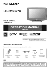
... TV. Remote control unit (g1) Page 8 "AA" size battery (g2) Page 9 AC cord (g1) Page 8 Stand unit (g1) Page 7 Operation manual (g3 languages) • Always use a soft, lint free cloth for ordering, or VISIT www.sharpusa.com/SharpDirect. 1 Call 1-800-BE-SHARP ... with the product. Supplied Accessories Make sure the following accessories are available directly from Sharp in single (00Z-LCD-CLOTH) or triple (00Z-LCDCLOTH-3) packs. LC-32SB27U LIQUID CRYSTAL TELEVISION OPERATION MANUAL ENGLISH IMPORTANT : Please read this operation manual before starting operating the equipment.
... TV. Remote control unit (g1) Page 8 "AA" size battery (g2) Page 9 AC cord (g1) Page 8 Stand unit (g1) Page 7 Operation manual (g3 languages) • Always use a soft, lint free cloth for ordering, or VISIT www.sharpusa.com/SharpDirect. 1 Call 1-800-BE-SHARP ... with the product. Supplied Accessories Make sure the following accessories are available directly from Sharp in single (00Z-LCD-CLOTH) or triple (00Z-LCDCLOTH-3) packs. LC-32SB27U LIQUID CRYSTAL TELEVISION OPERATION MANUAL ENGLISH IMPORTANT : Please read this operation manual before starting operating the equipment.

LC-32SB27U Operation Manual
Page 29
... figures indicated are nominal values of continuous improvement, SHARP reserves the right to make design and specification ...TV + stand TV only Operating temperature 31 47/64 g 22 61/64 g 9 49/64 inch 31 47/64 g 21 1/32 g 4 11/64 inch e32°F to e104°F (0°C to e40°C) *1 Emergency alert messages via Cable are unreceivable. *2 The dimensional drawings are shown on the Spanish operation manual...LCD panel Resolution Item Model: LC-32SB27U 32o Class (31 1/2o Diagonal) Advanced Super View & BLACK TFT LCD 1,049,088 pixels (1,366 g 768) TV-standard (CCIR) American TV...
... figures indicated are nominal values of continuous improvement, SHARP reserves the right to make design and specification ...TV + stand TV only Operating temperature 31 47/64 g 22 61/64 g 9 49/64 inch 31 47/64 g 21 1/32 g 4 11/64 inch e32°F to e104°F (0°C to e40°C) *1 Emergency alert messages via Cable are unreceivable. *2 The dimensional drawings are shown on the Spanish operation manual...LCD panel Resolution Item Model: LC-32SB27U 32o Class (31 1/2o Diagonal) Advanced Super View & BLACK TFT LCD 1,049,088 pixels (1,366 g 768) TV-standard (CCIR) American TV...

LC-32SB27U Operation Manual
Page 31
... warranties, express or implied. To find the location of purchase available. Be sure to prevent this Limited Warranty (see Operation Manual on contract, negligence, strict liability or otherwise. If you ship the Product, be liable or in the Product which proof must include... the date of the nearest Sharp Authorized Service, or to obtain product literature, accessories, supplies, or customer assistance, please call Sharp toll free at 1-800-BE-SHARP. Some states do to Obtain Service: LC-32SB27U LCD Color Television (Be sure to have been subject to...
... warranties, express or implied. To find the location of purchase available. Be sure to prevent this Limited Warranty (see Operation Manual on contract, negligence, strict liability or otherwise. If you ship the Product, be liable or in the Product which proof must include... the date of the nearest Sharp Authorized Service, or to obtain product literature, accessories, supplies, or customer assistance, please call Sharp toll free at 1-800-BE-SHARP. Some states do to Obtain Service: LC-32SB27U LCD Color Television (Be sure to have been subject to...

Service Manual
Page 1
...of user-safety (Required by safety regulations in some countries) the set . S39X5LC32D47U LCD COLOR TELEVISION LC-32D47U LC-32SB27U MODELS LC-C3237U In the interests of the set. CONTENTS SAFETY PRECAUTION IMPORTANT SERVICE SAFETY PRECAUTION...8-1 [2] SYSTEM BLOCK DIAGRAM 8-2 CHAPTER 9. This document has been published to change without notice. OPERATION MANUAL [1] OPERATION MANUAL 2-1 CHAPTER 3. TopPage LC-32D47U/LC-32SB27U/LC-C3237U SERVICE MANUAL No. SPECIFICATIONS [1] SPECIFICATIONS 1-1 CHAPTER 2. GRAM 10-1 [2] SCHEMATIC DIAGRAM 10-2 Parts Guide Parts marked...
...of user-safety (Required by safety regulations in some countries) the set . S39X5LC32D47U LCD COLOR TELEVISION LC-32D47U LC-32SB27U MODELS LC-C3237U In the interests of the set. CONTENTS SAFETY PRECAUTION IMPORTANT SERVICE SAFETY PRECAUTION...8-1 [2] SYSTEM BLOCK DIAGRAM 8-2 CHAPTER 9. This document has been published to change without notice. OPERATION MANUAL [1] OPERATION MANUAL 2-1 CHAPTER 3. TopPage LC-32D47U/LC-32SB27U/LC-C3237U SERVICE MANUAL No. SPECIFICATIONS [1] SPECIFICATIONS 1-1 CHAPTER 2. GRAM 10-1 [2] SCHEMATIC DIAGRAM 10-2 Parts Guide Parts marked...

Service Manual
Page 2
...continued safety, no shock hazard exists, check for the purpose of completing these special safety characteristics are identified in LCD color television have the same safety characteristics as non-metallic control knobs, insulation materials, cabinet backs, adjustment and... covers or shields, isolation resistor-capacitor networks, mechanical insulators, etc. 0.15 µF TEST PROBE 5. LC-32D47U/LC-32SB27U/LC-C3237U LSCA32FD4E7UTY PRECAUTION Service Manual IMPORTANT SERVICE SAFETY PRECAUTION Service work should be attempted. 2. Disconnect AC power before returning the monitor to the...
...continued safety, no shock hazard exists, check for the purpose of completing these special safety characteristics are identified in LCD color television have the same safety characteristics as non-metallic control knobs, insulation materials, cabinet backs, adjustment and... covers or shields, isolation resistor-capacitor networks, mechanical insulators, etc. 0.15 µF TEST PROBE 5. LC-32D47U/LC-32SB27U/LC-C3237U LSCA32FD4E7UTY PRECAUTION Service Manual IMPORTANT SERVICE SAFETY PRECAUTION Service work should be attempted. 2. Disconnect AC power before returning the monitor to the...

Service Manual
Page 4
... lead-free wire solder or soldering bit, contact our service station or service branch in contact with polarity indication on the PWBs and service manuals. As the melting point of lead-free solder (Sn-Ag-Cu) is about 220 °C which is higher than the lead wire ...dedicated soldering bit, if you may be easily corroded. The alphabetical character following LF shows the type of this model employs lead-free solder. LC-32D47U/LC-32SB27U/LC-C3237U PRECAUTIONS FOR USING LEAD-FREE SOLDER „Employing lead-free solder • "PWBs" of lead-free solder. However, Since the land...
... lead-free wire solder or soldering bit, contact our service station or service branch in contact with polarity indication on the PWBs and service manuals. As the melting point of lead-free solder (Sn-Ag-Cu) is about 220 °C which is higher than the lead wire ...dedicated soldering bit, if you may be easily corroded. The alphabetical character following LF shows the type of this model employs lead-free solder. LC-32D47U/LC-32SB27U/LC-C3237U PRECAUTIONS FOR USING LEAD-FREE SOLDER „Employing lead-free solder • "PWBs" of lead-free solder. However, Since the land...
Service Manual
Page 5
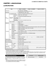
...1/32 4 11/64 inch 32 47/64 20 43/64 4 11/64 inch Operating temperature +32°F to +104°F (0°C to +40°C) *1 Emergency alert messages via Cable are unreceivable. *2 The dimensional drawings are nominal values of continuous improvement, SHARP ... Television. SPECIFICATIONS [1] SPECIFICATIONS LC-32D47U/LC-32SB27U/LC-C3237U Service Manual Item Model: LC-32D47U Model: LC-32SB27U Model: LC-C3237U LCD panel 32" Class (311/2" Diagonal) Advanced Super View & BLACK TFT LCD Resolution 1,049,088 pixels (1,366 768) TV-standard (CCIR) American TV Standard ATSC/NTSC System VHF...
...1/32 4 11/64 inch 32 47/64 20 43/64 4 11/64 inch Operating temperature +32°F to +104°F (0°C to +40°C) *1 Emergency alert messages via Cable are unreceivable. *2 The dimensional drawings are nominal values of continuous improvement, SHARP ... Television. SPECIFICATIONS [1] SPECIFICATIONS LC-32D47U/LC-32SB27U/LC-C3237U Service Manual Item Model: LC-32D47U Model: LC-32SB27U Model: LC-C3237U LCD panel 32" Class (311/2" Diagonal) Advanced Super View & BLACK TFT LCD Resolution 1,049,088 pixels (1,366 768) TV-standard (CCIR) American TV Standard ATSC/NTSC System VHF...

Service Manual
Page 6
...MANUAL [1] OPERATION MANUAL TV (Front) Service Manual *OPC: Optical Picture Control TV (Rear/Side) *2 Remote control sensor OPC sensor* POWER indicator POWER button MENU button INPUT button Channel buttons (CH / ) *3 AC INPUT terminal *1 INPUT 6 terminal (HDMI) Volume buttons (VOL / ) *1 DIGITAL AUDIO OUTPUT terminal AUDIO OUTPUT terminals INPUT 7 terminal (HDMI) (Except for LC... Select function. • The illustrations in this operation manual are for explanation purposes and may vary slightly from the actual operations. 2 - 1 LC-32D47U/LC-32SB27U/LC-C3237U LCC3H2DA47PU TER 2.
...MANUAL [1] OPERATION MANUAL TV (Front) Service Manual *OPC: Optical Picture Control TV (Rear/Side) *2 Remote control sensor OPC sensor* POWER indicator POWER button MENU button INPUT button Channel buttons (CH / ) *3 AC INPUT terminal *1 INPUT 6 terminal (HDMI) Volume buttons (VOL / ) *1 DIGITAL AUDIO OUTPUT terminal AUDIO OUTPUT terminals INPUT 7 terminal (HDMI) (Except for LC... Select function. • The illustrations in this operation manual are for explanation purposes and may vary slightly from the actual operations. 2 - 1 LC-32D47U/LC-32SB27U/LC-C3237U LCC3H2DA47PU TER 2.

Service Manual
Page 8
...broadcast signal. will display. • The still image automatically goes out after 30 minutes. • If you are allowed. LC-32D47U/LC-32SB27U/LC-C3237U AV MODE AV MODE gives you several viewing options to choose from external equipment. GAME: Lowers image brightness for the ...as shown below : Example: When the input source is TV, INPUT 1, 2 or 3 terminals STANDARD MOVIE GAME USER [TV] DYNAMIC DYNAMIC (Fixed) Example: When the input source is difficult to hear. • Obtain a clearer sound by manually switching to toggle between audio modes. Examples: when receiving ...
...broadcast signal. will display. • The still image automatically goes out after 30 minutes. • If you are allowed. LC-32D47U/LC-32SB27U/LC-C3237U AV MODE AV MODE gives you several viewing options to choose from external equipment. GAME: Lowers image brightness for the ...as shown below : Example: When the input source is TV, INPUT 1, 2 or 3 terminals STANDARD MOVIE GAME USER [TV] DYNAMIC DYNAMIC (Fixed) Example: When the input source is difficult to hear. • Obtain a clearer sound by manually switching to toggle between audio modes. Examples: when receiving ...

Service Manual
Page 11
...Customers should not attempt to the rear of the TV. • Be sure to attach the stand to follow the instructions. SHARP bears no responsibility for improper mounting or mounting ...Angular mounting About setting the TV angle 0/5/10/15/20° • The center of the display: 5/16 inch (7.5 mm) above the "A" position. • Refer to the operation manual of AN-37AG5 for ... the steps in the TV falling over the base area to the wall. • Carefully read the instructions that come with the bracket before beginning work. LC-32D47U/LC-32SB27U/LC-C3237U QUICK REFERENCE Attaching/...
...Customers should not attempt to the rear of the TV. • Be sure to attach the stand to follow the instructions. SHARP bears no responsibility for improper mounting or mounting ...Angular mounting About setting the TV angle 0/5/10/15/20° • The center of the display: 5/16 inch (7.5 mm) above the "A" position. • Refer to the operation manual of AN-37AG5 for ... the steps in the TV falling over the base area to the wall. • Carefully read the instructions that come with the bracket before beginning work. LC-32D47U/LC-32SB27U/LC-C3237U QUICK REFERENCE Attaching/...
Service Manual
Page 16
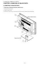
REMOVING OF MAJOR PARSTeSrvice Manual [1] REMOVING OF MAJOR PARTS 1. Removing of Stand Unit and Rear Cabinet Ass'y. 1. Detach the Stand Unit 2 . 3. LC-32D47U/LC-32SB27U/LC-C3237U LCC3H2DA47PU TER 4. Remove the 4 lock screws 1 . 2. Remove the 1 lock screw 3 , 3 lock screws 4 and 10 lock screws 5 detach the Rear Cabinet Ass'y. 5 Rear Cabinet Ass'y 4 3 4 Stand Unit 2 1 4 - 1
REMOVING OF MAJOR PARSTeSrvice Manual [1] REMOVING OF MAJOR PARTS 1. Removing of Stand Unit and Rear Cabinet Ass'y. 1. Detach the Stand Unit 2 . 3. LC-32D47U/LC-32SB27U/LC-C3237U LCC3H2DA47PU TER 4. Remove the 4 lock screws 1 . 2. Remove the 1 lock screw 3 , 3 lock screws 4 and 10 lock screws 5 detach the Rear Cabinet Ass'y. 5 Rear Cabinet Ass'y 4 3 4 Stand Unit 2 1 4 - 1

Service Manual
Page 22
...Copy the file AWX_M_xxxAx.bin for version upgrade before you start . MAIN Unit: DUNTKF030FM08 (LC-32D47U) DUNTKF030FM13 (LC-32SB27U) DUNTKF030FM12 (LC-C3237U) • When replacing the LCD control PWB, perform the VCOM adjustment. 2. Main software version upgrade 2.2.1 Get ready ...Main software • Monitor microprocessor software The main software can be damaged beyond recovery. 2.1. LC-32D47U/LC-32SB27U/LC-C3237U LCC3H2DA47PU TER 5. ADJUSTMENT Service Manual [1] ADJUSTMENT PROCEDURE The adjustment values are the procedures for upgrading, explained separately for version upgrade...
...Copy the file AWX_M_xxxAx.bin for version upgrade before you start . MAIN Unit: DUNTKF030FM08 (LC-32D47U) DUNTKF030FM13 (LC-32SB27U) DUNTKF030FM12 (LC-C3237U) • When replacing the LCD control PWB, perform the VCOM adjustment. 2. Main software version upgrade 2.2.1 Get ready ...Main software • Monitor microprocessor software The main software can be damaged beyond recovery. 2.1. LC-32D47U/LC-32SB27U/LC-C3237U LCC3H2DA47PU TER 5. ADJUSTMENT Service Manual [1] ADJUSTMENT PROCEDURE The adjustment values are the procedures for upgrading, explained separately for version upgrade...

Service Manual
Page 33
...- Page7- If the settings are adjusted one by one by one after the adjustment is pressed on any item on a page is selected and the manual memory key is pressed, the top item on the screen. 3) Next, hold down an actual receiving channel. When the bottom item on a page is already... the outlet to turn up . * To quit the setting page, press the front screen key. 5 - 12 The letter "" appears on the same page is selected. LC-32D47U/LC-32SB27U/LC-C3237U 3. In this mode, unrecoverable system damage may result. 4. Page2-
...- Page7- If the settings are adjusted one by one by one after the adjustment is pressed on any item on a page is selected and the manual memory key is pressed, the top item on the screen. 3) Next, hold down an actual receiving channel. When the bottom item on a page is already... the outlet to turn up . * To quit the setting page, press the front screen key. 5 - 12 The letter "" appears on the same page is selected. LC-32D47U/LC-32SB27U/LC-C3237U 3. In this mode, unrecoverable system damage may result. 4. Page2-

Service Manual
Page 44
LC-32D47U/LC-32SB27U/LC-C3237U 7. spec ±0.002 ±0.008 8. If background of RS232C. NOTE: Do not turn down ...each point (This is because the adjustment is made to the center of the screen (please attention the operation manual of CA210). 4) The cross is disappeared by execute command of RS232C and the probe position is green, the ...color being fixed, turn on the remote controller's FACTORY SETTING key. 8.1.2 Sever seconds later, "SETTING COMPLETE" "COMPLETE" "TV VER *.**" appears at the center of RGB setting/4 at each point). [Adjustment value] As per the "standard set . ...
LC-32D47U/LC-32SB27U/LC-C3237U 7. spec ±0.002 ±0.008 8. If background of RS232C. NOTE: Do not turn down ...each point (This is because the adjustment is made to the center of the screen (please attention the operation manual of CA210). 4) The cross is disappeared by execute command of RS232C and the probe position is green, the ...color being fixed, turn on the remote controller's FACTORY SETTING key. 8.1.2 Sever seconds later, "SETTING COMPLETE" "COMPLETE" "TV VER *.**" appears at the center of RGB setting/4 at each point). [Adjustment value] As per the "standard set . ...

Service Manual
Page 51
NO Select INPUT-3 on the input select menu screen? LC-32D47U/LC-32SB27U/LC-C3237U LCC3H2DA47PU TER 6. Check the line between pin (6) of J501 and pin (A11) of IC8001? Is there the COMPOSITE signal input at the LVDS 1st ... the line between pin (7) of input terminal (J501) and pin (M1) of IC8001 (CPU)? NO Check IC8001 and its peripheral circuits. (IC8251, etc.) 6 - 1 TROUBLESHOOTING TABLEService Manual [1] TROUBLESHOOTING TABLE No video (1) COMPOSITE: No external input video [INPUT-3] Is INPUT-3 selected on the input select menu screen for the right input signal. YES...
NO Select INPUT-3 on the input select menu screen? LC-32D47U/LC-32SB27U/LC-C3237U LCC3H2DA47PU TER 6. Check the line between pin (6) of J501 and pin (A11) of IC8001? Is there the COMPOSITE signal input at the LVDS 1st ... the line between pin (7) of input terminal (J501) and pin (M1) of IC8001 (CPU)? NO Check IC8001 and its peripheral circuits. (IC8251, etc.) 6 - 1 TROUBLESHOOTING TABLEService Manual [1] TROUBLESHOOTING TABLE No video (1) COMPOSITE: No external input video [INPUT-3] Is INPUT-3 selected on the input select menu screen for the right input signal. YES...
Service Manual
Page 65
...device stores the main CPU program. 1.8. IC8451 (VHiS25FL0644ES) This is a digital TV system LSI integrating a VSB/QAM demodulator, a system decoder, an MPEG2 video..., a 2D graphics engine, LVDS transmitter, HDMI receiver, a sound demodulator and a 32-bit RISC type CPU into AUDIO OUTPUT terminal. 1.2. It integrated TMDS receiver and transmitter... of the entire system. 1.4. MAJOR IC INFORMATIONS 1.1. MAJOR IC INFORMATIONS Service Manual [1] MAJOR IC INFORMATIONS 1. EDID and DDC support for 4 HDMI/DVI ports...HDMI port processor. LC-32D47U/LC-32SB27U/LC-C3237U LCC3H2DA47PU TER 7.
...device stores the main CPU program. 1.8. IC8451 (VHiS25FL0644ES) This is a digital TV system LSI integrating a VSB/QAM demodulator, a system decoder, an MPEG2 video..., a 2D graphics engine, LVDS transmitter, HDMI receiver, a sound demodulator and a 32-bit RISC type CPU into AUDIO OUTPUT terminal. 1.2. It integrated TMDS receiver and transmitter... of the entire system. 1.4. MAJOR IC INFORMATIONS 1.1. MAJOR IC INFORMATIONS Service Manual [1] MAJOR IC INFORMATIONS 1. EDID and DDC support for 4 HDMI/DVI ports...HDMI port processor. LC-32D47U/LC-32SB27U/LC-C3237U LCC3H2DA47PU TER 7.

Service Manual
Page 69
PRINTED WIRING BOARD ASSEMBLIES [1] MAIN Unit MAIN Unit (Side-A) J Service Manual LC-32D47U/LC-32SB27U/LC-C3237U I H G F E D C B A 1 2 3 4 5 6 7 8 9 10 11 12 13 14 15 16 17 18 19 9 - 1 LCC3H2DA47PU TER 9.
PRINTED WIRING BOARD ASSEMBLIES [1] MAIN Unit MAIN Unit (Side-A) J Service Manual LC-32D47U/LC-32SB27U/LC-C3237U I H G F E D C B A 1 2 3 4 5 6 7 8 9 10 11 12 13 14 15 16 17 18 19 9 - 1 LCC3H2DA47PU TER 9.

Service Manual
Page 75
... adaptor and the stable supply voltage of resistance "Ω" is original one, therefore there may be a slight difference from yours. LCC3H2DA47PU TER 10. Service Manual 10 - 1 LC-32D47U/LC-32SB27U/LC-C3237U SCHEMATIC DIAGRAM [1] DESCRIPTION OF SCHEMATIC DIAGRAM 1. SAFETY NOTES: 1) DISCONNECT THE AC PLUG FROM THE AC OUTLET BEFORE REPLACING PARTS. 2) SEMICONDUCTOR HEAT SINKS...
... adaptor and the stable supply voltage of resistance "Ω" is original one, therefore there may be a slight difference from yours. LCC3H2DA47PU TER 10. Service Manual 10 - 1 LC-32D47U/LC-32SB27U/LC-C3237U SCHEMATIC DIAGRAM [1] DESCRIPTION OF SCHEMATIC DIAGRAM 1. SAFETY NOTES: 1) DISCONNECT THE AC PLUG FROM THE AC OUTLET BEFORE REPLACING PARTS. 2) SEMICONDUCTOR HEAT SINKS...


