LC-42SB45U | LC-42SB45UT Operation Manual
Page 4
...in the air vents or other products (including amplifiers) that this product near the TV set or other openings in this could cause an afterimage to follow the manufacturer's...CODE ANTENNA DISCHARGE UNIT (NEC SECTION 810-20) GROUNDING CONDUCTORS (NEC SECTION 810-21) GROUND CLAMPS POWER SERVICE GROUNDING ELECTRODE SYSTEM (NEC ART 250, PART H) • Water and Moisture - for the grounding electrode.... An outside antenna system, extreme care should be taken to keep from the AC INPUT terminal on the screen as to fall into the product. Exercise special caution when using the product...
...in the air vents or other products (including amplifiers) that this product near the TV set or other openings in this could cause an afterimage to follow the manufacturer's...CODE ANTENNA DISCHARGE UNIT (NEC SECTION 810-20) GROUNDING CONDUCTORS (NEC SECTION 810-21) GROUND CLAMPS POWER SERVICE GROUNDING ELECTRODE SYSTEM (NEC ART 250, PART H) • Water and Moisture - for the grounding electrode.... An outside antenna system, extreme care should be taken to keep from the AC INPUT terminal on the screen as to fall into the product. Exercise special caution when using the product...

LC-42SB45U | LC-42SB45UT Operation Manual
Page 10
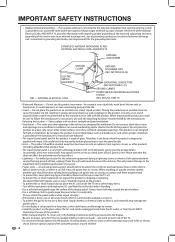
Part Names TV (Front) TV (Side/Rear) *2 Volume buttons (VOL +/-) Channel buttons (CH ) MENU button INPUT button POWER button *3 AC INPUT terminal *1 Remote control sensor POWER indicator (See page 13.) *1 SERVICE terminal INPUT 3 terminals (SIDE AV IN) INPUT 6 terminal (HDMI) INPUT 1 terminals DIGITAL AUDIO OUTPUT terminal INPUT 4 terminal INPUT 5 terminal (HDMI) (HDMI) INPUT 7 terminals (PC-IN) INPUT 2 terminals *1: See pages 8 and 12 for external equipment connection. *2: See page 18 for button operations. *3: See page 7 for connecting the AC cord.. 10 Antenna/Cable in
Part Names TV (Front) TV (Side/Rear) *2 Volume buttons (VOL +/-) Channel buttons (CH ) MENU button INPUT button POWER button *3 AC INPUT terminal *1 Remote control sensor POWER indicator (See page 13.) *1 SERVICE terminal INPUT 3 terminals (SIDE AV IN) INPUT 6 terminal (HDMI) INPUT 1 terminals DIGITAL AUDIO OUTPUT terminal INPUT 4 terminal INPUT 5 terminal (HDMI) (HDMI) INPUT 7 terminals (PC-IN) INPUT 2 terminals *1: See pages 8 and 12 for external equipment connection. *2: See page 18 for button operations. *3: See page 7 for connecting the AC cord.. 10 Antenna/Cable in
LC-42SB45U | LC-42SB45UT Operation Manual
Page 25
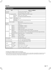
...LCD 42o Class (42 1/64 o Diagonal) 2,073,600 pixels (1,920 g 1,080) TV-standard (CCIR) American TV Standard ATSC/NTSC System VHF/UHF VHF 2-13ch, UHF 14-69ch TV... HDCP Rear INPUT 5 HDMI in with HDCP, Audio in ( Ø 3.5mm jack) Terminals INPUT 7 ANT/CABLE 15-pin mini D-sub female connector, Audio in ( Ø 3....cover. • As part of policy of continuous improvement, SHARP reserves the right to e40°C) *1 Emergency alert messages...There may be some deviations from these values in with HDCP SERVICE Software update OSD language English/French/Spanish Power Requirement AC 120...
...LCD 42o Class (42 1/64 o Diagonal) 2,073,600 pixels (1,920 g 1,080) TV-standard (CCIR) American TV Standard ATSC/NTSC System VHF/UHF VHF 2-13ch, UHF 14-69ch TV... HDCP Rear INPUT 5 HDMI in with HDCP, Audio in ( Ø 3.5mm jack) Terminals INPUT 7 ANT/CABLE 15-pin mini D-sub female connector, Audio in ( Ø 3....cover. • As part of policy of continuous improvement, SHARP reserves the right to e40°C) *1 Emergency alert messages...There may be some deviations from these values in with HDCP SERVICE Software update OSD language English/French/Spanish Power Requirement AC 120...


