

Operater's Manual
Page 3
.../Adding Fuel 23 Fuel Filter 23 t Oil & Filter Change 23 c Lubrication 24 o u Check Transmission Oil Level 25 Transmission Oil Filter Change 25 N d Servicing the Mower Blades 26 Ground Speed Control Lever Adjustment 28 o Speed Balancing Adjustment 28 r Neutral Adjustment 28 p Parking Brake Adjustment 29 Return to Neutral Adjustment 30 e Deck Rod...
.../Adding Fuel 23 Fuel Filter 23 t Oil & Filter Change 23 c Lubrication 24 o u Check Transmission Oil Level 25 Transmission Oil Filter Change 25 N d Servicing the Mower Blades 26 Ground Speed Control Lever Adjustment 28 o Speed Balancing Adjustment 28 r Neutral Adjustment 28 p Parking Brake Adjustment 29 Return to Neutral Adjustment 30 e Deck Rod...

Operater's Manual
Page 5
... if the system does not pass all the safety interlock system tests found in this machine. r n Thrown Objects fo tio This unit has spinning mower blades. o u Do not operate this equipment safely, it is running ! Keep safety devices (guards, shields, and switches) in the area while the unit is... zone (stay seated in the seat), and follow the safety rules in place. Operator Safety Slope Operation Operation on slopes can be thrown by the blade BEFORE you t c start mowing. You should not operate on can cause sliding and loss of steering, control, and possible rollover. It's not worth...
... if the system does not pass all the safety interlock system tests found in this machine. r n Thrown Objects fo tio This unit has spinning mower blades. o u Do not operate this equipment safely, it is running ! Keep safety devices (guards, shields, and switches) in the area while the unit is... zone (stay seated in the seat), and follow the safety rules in place. Operator Safety Slope Operation Operation on slopes can be thrown by the blade BEFORE you t c start mowing. You should not operate on can cause sliding and loss of steering, control, and possible rollover. It's not worth...
Operater's Manual
Page 7
...look down and use caution when making turns and when changing directions on hillsides. Turn off engine before starting . Stop equipment and inspect blades after striking objects or abnormal vibration occurs. Do 17. Do not operate unless they are explosive. To reduce fire hazard, keep pets ... switch to cool before dismounting. Make necessary repairs b) Never remove fuel cap or add fuel with the blades running. 10. running unit unattended. Allow engine to disengage the blades when not mowing. 12. not smoke. 18. clear path. 19. Do not operate the unit while...
...look down and use caution when making turns and when changing directions on hillsides. Turn off engine before starting . Stop equipment and inspect blades after striking objects or abnormal vibration occurs. Do 17. Do not operate unless they are explosive. To reduce fire hazard, keep pets ... switch to cool before dismounting. Make necessary repairs b) Never remove fuel cap or add fuel with the blades running. 10. running unit unattended. Allow engine to disengage the blades when not mowing. 12. not smoke. 18. clear path. 19. Do not operate the unit while...
Operater's Manual
Page 8
... children, even with grass catchers or other attachments. Watch for small children. 4. Uneven terrain could cause sliding. Use extra care with the blade(s) off the slope. Do not make sudden changes in effective working order. See your foot on Authorized Service Dealer to operate the unit. ...a spark arrester the ground. (ride-on units) designed for the relevant Emissions Durability Period and Air Index information on a slope), disengage the blade(s) (PTO) and drive slow off . Never assume that may require the use or operate the engine in any forest-covered, brush-covered, ...
... children, even with grass catchers or other attachments. Watch for small children. 4. Uneven terrain could cause sliding. Use extra care with the blade(s) off the slope. Do not make sudden changes in effective working order. See your foot on Authorized Service Dealer to operate the unit. ...a spark arrester the ground. (ride-on units) designed for the relevant Emissions Durability Period and Air Index information on a slope), disengage the blade(s) (PTO) and drive slow off . Never assume that may require the use or operate the engine in any forest-covered, brush-covered, ...
Operater's Manual
Page 9
..., or motors: WARNING: Hydraulic fluid escaping under high pressure. Disconnect the negative terminal first and the positive last. Wrap the blade(s) or wear gloves, and use extreme care when removing the cap. Grass catcher components are explosive. 13. Only authorized service locations...your authorized dealer. 26. Never tamper with factory specifications on a truck bed with the rim of Gasoline 1. Use care when checking blades. If possible, do not store near flame. 7 Check brake operation frequently. Always comply with safety devices. To prevent serious bodily ...
..., or motors: WARNING: Hydraulic fluid escaping under high pressure. Disconnect the negative terminal first and the positive last. Wrap the blade(s) or wear gloves, and use extreme care when removing the cap. Grass catcher components are explosive. 13. Only authorized service locations...your authorized dealer. 26. Never tamper with factory specifications on a truck bed with the rim of Gasoline 1. Use care when checking blades. If possible, do not store near flame. 7 Check brake operation frequently. Always comply with safety devices. To prevent serious bodily ...

Operater's Manual
Page 11
... belt does not stop within five (5) seconds, see your dealer. WARNING This indicates a hazard which, if not avoided, could be locked in Blade Keep Children Away Slippery • Parking brake is turned off (or operator rises off , parking brake must be engaged, and the motion control ...Slopes must be damaged. Safety RNeopt roduc Icon Hazard Alert Safety Icon Toxic Fumes Read the Manual Open Flame Hazard Amputation: Foot in Blade Amputation: Hand in the Fire Hazard Rollover NEUTRAL position after electric PTO switch is engaged, AND • Ground speed control levers ...
... belt does not stop within five (5) seconds, see your dealer. WARNING This indicates a hazard which, if not avoided, could be locked in Blade Keep Children Away Slippery • Parking brake is turned off (or operator rises off , parking brake must be engaged, and the motion control ...Slopes must be damaged. Safety RNeopt roduc Icon Hazard Alert Safety Icon Toxic Fumes Read the Manual Open Flame Hazard Amputation: Foot in Blade Amputation: Hand in the Fire Hazard Rollover NEUTRAL position after electric PTO switch is engaged, AND • Ground speed control levers ...
Operater's Manual
Page 22
...grass off more quickly than 2 to allow freer circulation of lawn previously cut , mow across the lawn in a single pass 20 www.snapper.com Mow at time of the grass greatly affect the results you are mowing too or slower for Broadcasting Always operate the engine at ... fences and buildings, and conditions such as slopes and fo tio grades must also be done in the opposite direction so that 1 inch of the blades and prevents many common cutting problems. Use an appropriate ground speed for manual gear models). Engine Speed & Ground Speed for manual gear models). problems...
...grass off more quickly than 2 to allow freer circulation of lawn previously cut , mow across the lawn in a single pass 20 www.snapper.com Mow at time of the grass greatly affect the results you are mowing too or slower for Broadcasting Always operate the engine at ... fences and buildings, and conditions such as slopes and fo tio grades must also be done in the opposite direction so that 1 inch of the blades and prevents many common cutting problems. Use an appropriate ground speed for manual gear models). Engine Speed & Ground Speed for manual gear models). problems...

Operater's Manual
Page 23
...proper mulching operation. Ground speed while fo tio mulching should be dry and the the appropriate amount is matched to 3/4 inch of grass blade. This provides r short clippings which then blows them down INTO the lawn. Operation Proper Mulching Attaching A Trailer Mulching consists of a ... slippery surfaces can greatly reduce traction and the ability to cut . See SLOPE OPERATION and TOWED EQUIPMENT in the spring. The long grass blades, quick growth, and often wetter conditions are more horsepower t c than 10°. Secure the trailer with both the cutting height e...
...proper mulching operation. Ground speed while fo tio mulching should be dry and the the appropriate amount is matched to 3/4 inch of grass blade. This provides r short clippings which then blows them down INTO the lawn. Operation Proper Mulching Attaching A Trailer Mulching consists of a ... slippery surfaces can greatly reduce traction and the ability to cut . See SLOPE OPERATION and TOWED EQUIPMENT in the spring. The long grass blades, quick growth, and often wetter conditions are more horsepower t c than 10°. Secure the trailer with both the cutting height e...

Operater's Manual
Page 24
...Level Check Rider Brakes Every 25 Hours Check Rider / Mower for normal care of your rider and mower. Replace if damaged. 22 www.snapper.com You will need to Engine Owner's Operator's Manual Lubricate Rider & Mower* Service Air Filter Check Tire Pressure Change Oil & Filter ...Every 100 Hours Check Mower Blade Stopping Time r n Clean Battery & Cables Every 250 Hours fo tio Change Transmission Oil Filter* t ** More often in hot (over 85° ...
...Level Check Rider Brakes Every 25 Hours Check Rider / Mower for normal care of your rider and mower. Replace if damaged. 22 www.snapper.com You will need to Engine Owner's Operator's Manual Lubricate Rider & Mower* Service Air Filter Check Tire Pressure Change Oil & Filter ...Every 100 Hours Check Mower Blade Stopping Time r n Clean Battery & Cables Every 250 Hours fo tio Change Transmission Oil Filter* t ** More often in hot (over 85° ...

Operater's Manual
Page 28
... nicks, sharpen greater than .5" (12,7 mm) of the spindle shaft and remove the mower blade mounting bolt with new mower blade.) 26 www.snapper.com A worn or damaged blade can break, and a piece of the below r conditions. Inspecting the Mower Blade Tips A. If the cutting edges are no flats on the flats of the mower...
... nicks, sharpen greater than .5" (12,7 mm) of the spindle shaft and remove the mower blade mounting bolt with new mower blade.) 26 www.snapper.com A worn or damaged blade can break, and a piece of the below r conditions. Inspecting the Mower Blade Tips A. If the cutting edges are no flats on the flats of the mower...

Operater's Manual
Page 29
... original bevel (A, Figure 29) when grinding. ot uc 1. Check the balance of material from turning. Nail A B horizontal position. Tightening the Mower Blade for proper sharpening e instructions. Flat Washer C. Mower Blade Air Lift (Points Up For Installation) D. 4 X 4 Wooden Block 27 Secure with the air lifts pointing up towards the mower deck as shown...
... original bevel (A, Figure 29) when grinding. ot uc 1. Check the balance of material from turning. Nail A B horizontal position. Tightening the Mower Blade for proper sharpening e instructions. Flat Washer C. Mower Blade Air Lift (Points Up For Installation) D. 4 X 4 Wooden Block 27 Secure with the air lifts pointing up towards the mower deck as shown...

Operater's Manual
Page 34
...arm o (A, Figures 41). Lower the mower deck to -back. Carefully release the tension on the stationary idler pulley (B). A D 32 www.snapper.com Carefully rotate the breaker bar u CLOCKWISE, which will relieve the tension on the breaker bar. 5. Deck Drive Belt D. Remove the old... belts, DO NOT PRY BELTS OVER PULLEYS. 1. Idler Arm B. See Figure 40. Mower PTO Belt A. Reinstall the mower deck guards. 8. Mower blades are sharp. Injury may e result if the breaker bar is prematurely released while R the spring is being rotated. The front measurement should be 4" ...
...arm o (A, Figures 41). Lower the mower deck to -back. Carefully release the tension on the stationary idler pulley (B). A D 32 www.snapper.com Carefully rotate the breaker bar u CLOCKWISE, which will relieve the tension on the breaker bar. 5. Deck Drive Belt D. Remove the old... belts, DO NOT PRY BELTS OVER PULLEYS. 1. Idler Arm B. See Figure 40. Mower PTO Belt A. Reinstall the mower deck guards. 8. Mower blades are sharp. Injury may e result if the breaker bar is prematurely released while R the spring is being rotated. The front measurement should be 4" ...
Operater's Manual
Page 42
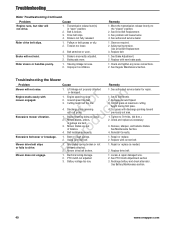
...Drive Belt Replacement 3. Ground speed too fast. c Blade mounting bolts are bent. o Belt installed incorrectly. Remove, sharpen, and balance blades. Battery voltage too low. 3. Troubleshooting Rider Troubleshooting ... easily with discharge pointing toward previously cut grass. Excessive mower vibration. o u Mower blades, arbors, or pulleys are loose. Cut grass with mower engaged. Tighten to full ...or oily. 2. Discharge chute jamming t with cut area. 1. N d Mower blades are out of balance. Decrease Ground Speed. 3. See authorized service dealer for repair....
...Drive Belt Replacement 3. Ground speed too fast. c Blade mounting bolts are bent. o Belt installed incorrectly. Remove, sharpen, and balance blades. Battery voltage too low. 3. Troubleshooting Rider Troubleshooting ... easily with discharge pointing toward previously cut grass. Excessive mower vibration. o u Mower blades, arbors, or pulleys are loose. Cut grass with mower engaged. Tighten to full ...or oily. 2. Discharge chute jamming t with cut area. 1. N d Mower blades are out of balance. Decrease Ground Speed. 3. See authorized service dealer for repair....

Operater's Manual
Page 43
... Deck is not leveled correctly. Check and inflate the tires. N d 6. Replace the blades. 4. Deck is not levelled correctly. 4. Blades are damaged. 1. Level the deck correctly. 2. Sharpen or replace the blades. 3. Repair or replace the deck. 6. Ground speed is too slow. 4. Sharpen your... is not leveled correctly. 2. Check and inflate the tires. 3. Repair or replace the spindle. 7. Reinstall the blades correctly. 8. Blades are not properly inflated. 8. Engine speed is damaged. 5. Clean out the mower. 6. Repair or replace the spindle. 6. Replace your...
... Deck is not leveled correctly. Check and inflate the tires. N d 6. Replace the blades. 4. Deck is not levelled correctly. 4. Blades are damaged. 1. Level the deck correctly. 2. Sharpen or replace the blades. 3. Repair or replace the deck. 6. Ground speed is too slow. 4. Sharpen your... is not leveled correctly. 2. Check and inflate the tires. 3. Repair or replace the spindle. 7. Reinstall the blades correctly. 8. Blades are not properly inflated. 8. Engine speed is damaged. 5. Clean out the mower. 6. Repair or replace the spindle. 6. Replace your...

Operater's Manual
Page 46
... do not provide proof of non-original parts is defective in our dealer locator map at WWW.SNAPPER. Once a product has experienced commercial use has exhausted the life of abuse such as filters, belts, cutting blades, and brake pads (except engine brake pads) are also excluded. Warranty service is permitted by purchaser... is described in materials or workmanship. This warranty also excludes failures due to you may not apply to the extent exclusion is available only through SNAPPER Authorized Service Dealers.
... do not provide proof of non-original parts is defective in our dealer locator map at WWW.SNAPPER. Once a product has experienced commercial use has exhausted the life of abuse such as filters, belts, cutting blades, and brake pads (except engine brake pads) are also excluded. Warranty service is permitted by purchaser... is described in materials or workmanship. This warranty also excludes failures due to you may not apply to the extent exclusion is available only through SNAPPER Authorized Service Dealers.

Parts Manual
Page 3
Rollers 6 48" Mower Deck Group - Housing, Covers, Spindles & Blades 8 48" Mower Deck Group - Pulleys, Belts & Idler Arm 10 Decals - Single Tank 28 Hydraulic Group 30 Instrument & Control Panel Group - Safety & ...Parking Brake Group r t i o Pump Drive Group Rear Bumper Group Seat Mount & Floor Group - S/N: 2016499707 & Above F u Wheel & Tire Group t d Wiring Schematic - 400Z Series S/N: 2016499706 & Below o o Wiring Schematic - 400Z Series S/N: 2016499707 & Above NR e p r Torque Specification Chart 34 36 40 42 44 46 48 50 52 54 56 Copyright © Briggs and Stratton...
Rollers 6 48" Mower Deck Group - Housing, Covers, Spindles & Blades 8 48" Mower Deck Group - Pulleys, Belts & Idler Arm 10 Decals - Single Tank 28 Hydraulic Group 30 Instrument & Control Panel Group - Safety & ...Parking Brake Group r t i o Pump Drive Group Rear Bumper Group Seat Mount & Floor Group - S/N: 2016499707 & Above F u Wheel & Tire Group t d Wiring Schematic - 400Z Series S/N: 2016499706 & Below o o Wiring Schematic - 400Z Series S/N: 2016499707 & Above NR e p r Torque Specification Chart 34 36 40 42 44 46 48 50 52 54 56 Copyright © Briggs and Stratton...

Parts Manual
Page 8
No: 5900528 NRo te pFroord u c t i o n Copyright © Briggs and Stratton. Housing, Covers, Spindles & Blades Note: Unless noted otherwise, use the standard torque specifications Mfg. All Rights reserved 8 29-Jul-2018 48" Mower Deck Group -
No: 5900528 NRo te pFroord u c t i o n Copyright © Briggs and Stratton. Housing, Covers, Spindles & Blades Note: Unless noted otherwise, use the standard torque specifications Mfg. All Rights reserved 8 29-Jul-2018 48" Mower Deck Group -

Parts Manual
Page 9
...SPRING, TORSION CAP, PROTECTOR, .120 ID 5600631 1 DECK SHELL W/ DECALS, 48" DECK, 400Z -(S/N: 2016167623 & ABOVE) 5410344A 1 PLATE, DEFLECTOR - BLK -(S/N: 2016167623 & ABOVE) Copyright © Briggs and Stratton. Housing, Covers, Spindles & Blades REF NO 1 2 3 4 5 6 7 8 9 10 11 12 13 14 15 ... 6 BOLT, 5/16-18 X 3/4 GD5 5025159 3 WASHER, 5/8 USS 5025320X14 3 BOLT, 5/8-11 X 1-3/4 GR8 5101004 1 SAFETY WALK, 4.00 X 7.50 5101986S 3 BLADES, SET OF THREE (3); 16.25 X.25 X 2.5, 1 X 3.5 5023156 12 BOLT, 5/16-18 X 1-1/4" FLANGE 5025392 14 NUT, 5/16-18 HEX NYLOCK FLANGE 5061095 ...
...SPRING, TORSION CAP, PROTECTOR, .120 ID 5600631 1 DECK SHELL W/ DECALS, 48" DECK, 400Z -(S/N: 2016167623 & ABOVE) 5410344A 1 PLATE, DEFLECTOR - BLK -(S/N: 2016167623 & ABOVE) Copyright © Briggs and Stratton. Housing, Covers, Spindles & Blades REF NO 1 2 3 4 5 6 7 8 9 10 11 12 13 14 15 ... 6 BOLT, 5/16-18 X 3/4 GD5 5025159 3 WASHER, 5/8 USS 5025320X14 3 BOLT, 5/8-11 X 1-3/4 GR8 5101004 1 SAFETY WALK, 4.00 X 7.50 5101986S 3 BLADES, SET OF THREE (3); 16.25 X.25 X 2.5, 1 X 3.5 5023156 12 BOLT, 5/16-18 X 1-1/4" FLANGE 5025392 14 NUT, 5/16-18 HEX NYLOCK FLANGE 5061095 ...

Parts Manual
Page 15
..., SAE 20W50 -(LOCATED UNDER SEAT PLATE) 5048970 1 DECAL, IGNITION CONTROL 5100342 1 DECAL, FUEL VALVE -(LOCATED ON BRACKET BEHIND RH SIDE OF SEAT) 5103196YP 1 DECAL, BELT & BLADE, S50X iCD -(LOCATED UNDER SEAT PLATE) 5101315 1 DECAL, CUT HEIGHT, S50X 5101991 2 DECAL, TRANSAXLE RELEASE -(LOCATED ON LH & RH DECK GUARDS) ----- 1 LABEL, EMISSION CONTROL CALIF...
..., SAE 20W50 -(LOCATED UNDER SEAT PLATE) 5048970 1 DECAL, IGNITION CONTROL 5100342 1 DECAL, FUEL VALVE -(LOCATED ON BRACKET BEHIND RH SIDE OF SEAT) 5103196YP 1 DECAL, BELT & BLADE, S50X iCD -(LOCATED UNDER SEAT PLATE) 5101315 1 DECAL, CUT HEIGHT, S50X 5101991 2 DECAL, TRANSAXLE RELEASE -(LOCATED ON LH & RH DECK GUARDS) ----- 1 LABEL, EMISSION CONTROL CALIF...

Parts Manual
Page 33
..., CONTROL PANEL - BLACK 1737853 1 SWITCH ASSEMBLY, Ignition Indak No Keys/Hdwr ----- 1 HOUR METER, ASSEMBLE -(S/N: 2015551938 & Above)(*See Footnote) 5102417 1 HOUR METER -(S/N: 2015551937 & Below) 5022180 1 SWITCH, BLADE ENGAGEMENT 5046501 1 CABLE, Choke Control, 47" -(Briggs & Stratton Models Only) 5047143 1 CABLE, CHOKE CONTROL, 39.5" 5025299X4SM 2 n 1717549 1 r t i o 1717550 1 1960547 1 o c 1737836 1 5025299X4SM 1 t F d u 1665238 1 NRo e p r o 5025126 1 -(Kawasaki...
..., CONTROL PANEL - BLACK 1737853 1 SWITCH ASSEMBLY, Ignition Indak No Keys/Hdwr ----- 1 HOUR METER, ASSEMBLE -(S/N: 2015551938 & Above)(*See Footnote) 5102417 1 HOUR METER -(S/N: 2015551937 & Below) 5022180 1 SWITCH, BLADE ENGAGEMENT 5046501 1 CABLE, Choke Control, 47" -(Briggs & Stratton Models Only) 5047143 1 CABLE, CHOKE CONTROL, 39.5" 5025299X4SM 2 n 1717549 1 r t i o 1717550 1 1960547 1 o c 1737836 1 5025299X4SM 1 t F d u 1665238 1 NRo e p r o 5025126 1 -(Kawasaki...


