Operater's Manual
Page 3
... and Controls 9 Operation 10 Before Starting 10 Operator Seat Adjustment 10 Starting Engine 11 Engaging Mower Blade 13 Engaging Wheel Drive 13 Stopping Engine, Wheel Drive, Blade 14 Setting Park Brake 15 Cutting Height Adjustment 15 Reverse Lockout Mechanism 16 Maintenance 17 Maintenance Chart ...18 Storage 23 fo tio Engine Adjustments and Repairs 24 Mower Deck and Component Adjustments 24 Rear Engine Rider Drive Components 27 t c Mower Blade Replacement 28 o Mower Drive Belt Replacement 29 u Battery 30 N d Troubleshooting 32 ro Warranty 34 Rep Slope Guide 35 ! Table ...
... and Controls 9 Operation 10 Before Starting 10 Operator Seat Adjustment 10 Starting Engine 11 Engaging Mower Blade 13 Engaging Wheel Drive 13 Stopping Engine, Wheel Drive, Blade 14 Setting Park Brake 15 Cutting Height Adjustment 15 Reverse Lockout Mechanism 16 Maintenance 17 Maintenance Chart ...18 Storage 23 fo tio Engine Adjustments and Repairs 24 Mower Deck and Component Adjustments 24 Rear Engine Rider Drive Components 27 t c Mower Blade Replacement 28 o Mower Drive Belt Replacement 29 u Battery 30 N d Troubleshooting 32 ro Warranty 34 Rep Slope Guide 35 ! Table ...
Operater's Manual
Page 4
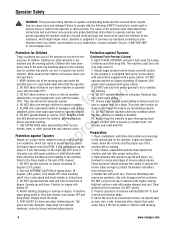
...and under the influence of -control and tip- DO NOT put your satisfaction, contact Customer Service (1-800-935-2967 or www.snapper.com). DO NOT operate machine on slopes with Add fuel outdoors only with engine running. slopes. washouts, culverts, fences and protruding objects...pets and hazards before starting , stopping or turning on slopes exceeding 10 degrees (18% watchful care of machine with the blade OFF). 3. DO NOT operate blades in accordance last saw them. Never assume that you will remain where you have to learn stops going down . these ...
...and under the influence of -control and tip- DO NOT put your satisfaction, contact Customer Service (1-800-935-2967 or www.snapper.com). DO NOT operate machine on slopes with Add fuel outdoors only with engine running. slopes. washouts, culverts, fences and protruding objects...pets and hazards before starting , stopping or turning on slopes exceeding 10 degrees (18% watchful care of machine with the blade OFF). 3. DO NOT operate blades in accordance last saw them. Never assume that you will remain where you have to learn stops going down . these ...
Operater's Manual
Page 5
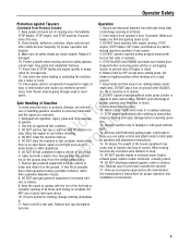
... loss of Gasoline To avoid personal injury or property damage, use accessories approved by the manufacturer. Check shields, deflectors, switches, blade controls and 3. feet on the ground. Extinguish all times until fueling is complete. ning. Watch out for emergencies. 6. Exercise... Safety Protection against a wall or obstruction. STOP other sources t c of 7. Protect yourself when mowing and wear safety glasses, 5. Blades must be OFF except when cutting grass. Set 12. If this is in contact with good artificial light. 13. Operate machine only...
... loss of Gasoline To avoid personal injury or property damage, use accessories approved by the manufacturer. Check shields, deflectors, switches, blade controls and 3. feet on the ground. Extinguish all times until fueling is complete. ning. Watch out for emergencies. 6. Exercise... Safety Protection against a wall or obstruction. STOP other sources t c of 7. Protect yourself when mowing and wear safety glasses, 5. Blades must be OFF except when cutting grass. Set 12. If this is in contact with good artificial light. 13. Operate machine only...
Operater's Manual
Page 6
... for weight less and deadly poison. Disconnect negative (black) cable from spark plug(s). 1. On slopes, the weight of control. 8. Wrap the blades in proper position. 13. r n tainer outdoors and away from binding. Check brakes frequently; Exhaust gases contain carbon monoxide, an odor- 2. ...injury. reduce fire hazard and engine overheating. 3. Use only factory authorized replacement parts or like parts when making repairs. 6 www.snapper.com DO NOT attach towed equipment except at the hitch 6. in an prevent controls from open flame, spark or pilot light ...
... for weight less and deadly poison. Disconnect negative (black) cable from spark plug(s). 1. On slopes, the weight of control. 8. Wrap the blades in proper position. 13. r n tainer outdoors and away from binding. Check brakes frequently; Exhaust gases contain carbon monoxide, an odor- 2. ...injury. reduce fire hazard and engine overheating. 3. Use only factory authorized replacement parts or like parts when making repairs. 6 www.snapper.com DO NOT attach towed equipment except at the hitch 6. in an prevent controls from open flame, spark or pilot light ...

Operater's Manual
Page 9
Transmission Shift Lever J. Engine Speed Control B. Cutting Height Lever C. Blade Pedal G. Blade Lever H. Fuel Tank 9 Clutch/Brake Pedal E. Park Brake Latch F. Features and Controls I . Ignition Switch D. Steering Wheel I J H G F E RNeopt rfoodr uctiBonA C D Features and Controls A. IMPORTANT The figures and illustrations in this manual are provided for reference only and may differ from your dealer if you have questions. Contact your specific model.
Transmission Shift Lever J. Engine Speed Control B. Cutting Height Lever C. Blade Pedal G. Blade Lever H. Fuel Tank 9 Clutch/Brake Pedal E. Park Brake Latch F. Features and Controls I . Ignition Switch D. Steering Wheel I J H G F E RNeopt rfoodr uctiBonA C D Features and Controls A. IMPORTANT The figures and illustrations in this manual are provided for reference only and may differ from your dealer if you have questions. Contact your specific model.
Operater's Manual
Page 10
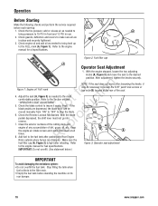
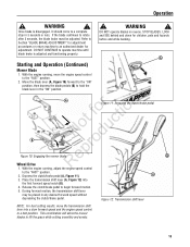
... (A, Figure 3) and move after loosening the knobs, it works freely. Adjust the seat (A, Figure 3) as needed to stop the blade. If the u blade pedals are in place and securely tightened. 3. Add fuel to the FULL mark (A, Figure 1). Check the tire pressure; Check engine ... can dissipate. Check the blade control to the engine manual for oil specifications. Operation Before Starting Make the following checks and perform the service required before standing the machine on its rear bumper. 10 www.snapper.com Figure 2: Fuel filler cap A Operator Seat Adjustment ...
... (A, Figure 3) and move after loosening the knobs, it works freely. Adjust the seat (A, Figure 3) as needed to stop the blade. If the u blade pedals are in place and securely tightened. 3. Add fuel to the FULL mark (A, Figure 1). Check the tire pressure; Check engine ... can dissipate. Check the blade control to the engine manual for oil specifications. Operation Before Starting Make the following checks and perform the service required before standing the machine on its rear bumper. 10 www.snapper.com Figure 2: Fuel filler cap A Operator Seat Adjustment ...
Operater's Manual
Page 11
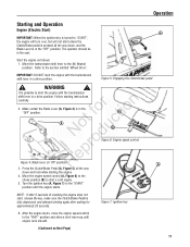
... carefully. NOTE: If after waiting for approximately 20 seconds. Refer to start unless the Clutch/Brake pedal is pressed all the way down , and the Blade Lever is in 'Off' position) A 3. A Figure 5: Engaging the clutch/brake pedal ! WARNING ! r n 2. IMPORTANT: DO NOT start the ...the engine starts, move the engine speed control to the "START" position until engine runs smooth. (Continued on Next Page) 11 Make certain the Blade Lever (A, Figure 4) is in a drive position. Press the Clutch/Brake Pedal (A, Figure 5) all the way down and hold while starting the ...
... carefully. NOTE: If after waiting for approximately 20 seconds. Refer to start unless the Clutch/Brake pedal is pressed all the way down , and the Blade Lever is in 'Off' position) A 3. A Figure 5: Engaging the clutch/brake pedal ! WARNING ! r n 2. IMPORTANT: DO NOT start the ...the engine starts, move the engine speed control to the "START" position until engine runs smooth. (Continued on Next Page) 11 Make certain the Blade Lever (A, Figure 4) is in a drive position. Press the Clutch/Brake Pedal (A, Figure 5) all the way down and hold while starting the ...
Operater's Manual
Page 12
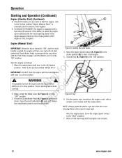
...! Follow starting instructions carefully. p 3. Should the battery be started with a smooth, even motion until the engine runs smooth. 12 www.snapper.com Move the engine speed control (A, Figure 6) to the choke position (B) to manually start the electric start unless the Clutch/Brake Pedal ...Operation (Continued) Engine (Electric Start) (Continued) A 8. fo tio IMPORTANT: DO NOT start the engine with the Park Brake engaged, and the Blade Lever is pulled, the engine will turn over, but will not start engines. 9. A Figure 9: Key 6. Press the Clutch/Brake Pedal (A, ...
...! Follow starting instructions carefully. p 3. Should the battery be started with a smooth, even motion until the engine runs smooth. 12 www.snapper.com Move the engine speed control (A, Figure 6) to the choke position (B) to manually start the electric start unless the Clutch/Brake Pedal ...Operation (Continued) Engine (Electric Start) (Continued) A 8. fo tio IMPORTANT: DO NOT start the engine with the Park Brake engaged, and the Blade Lever is pulled, the engine will turn over, but will not start engines. 9. A Figure 9: Key 6. Press the Clutch/Brake Pedal (A, ...
Operater's Manual
Page 13
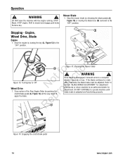
... adjustment. Depress the clutch/brake pedal (A, Figure 11). During forward motion, the transmission shift lever may be adjusted. If the blade continues to a complete stop in any desired forward speed without depressing the clutch/brake pedal. A Figure 11: Engaging the clutch/...brake pedal Not fodruction B pro Figure 10: Engaging the mower blade Re Wheel Drive A 1. Refer to Section "BLADE BRAKE ADJUSTMENT" for adjustment procedures or return machine to begin forward motion. 5. Place the transmission shift lever (A, Figure...
... adjustment. Depress the clutch/brake pedal (A, Figure 11). During forward motion, the transmission shift lever may be adjusted. If the blade continues to a complete stop in any desired forward speed without depressing the clutch/brake pedal. A Figure 11: Engaging the clutch/...brake pedal Not fodruction B pro Figure 10: Engaging the mower blade Re Wheel Drive A 1. Refer to Section "BLADE BRAKE ADJUSTMENT" for adjustment procedures or return machine to begin forward motion. 5. Place the transmission shift lever (A, Figure...
Operater's Manual
Page 14
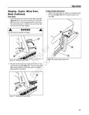
... Rear Engine Rider by turning the key (A, Figure 13) to rotate after 3 seconds, the blade brake must be adjusted. Figure 15: Stopping the mower blade ! Refer to Section "BLADE BRAKE ADJUSTMENT" for adjustment procedures or return machine to the "OFF" position. RepA Figure 14...: Engaging the clutch/brake pedal 14 www.snapper.com Operation ! Stop the mower blade by releasing the blade pedals (A, Figure 15) or moving the blade lever (B) rearward to an authorized dealer for adjustment. WARNING ! WARNING ! Shift to 'Off' ...
... Rear Engine Rider by turning the key (A, Figure 13) to rotate after 3 seconds, the blade brake must be adjusted. Figure 15: Stopping the mower blade ! Refer to Section "BLADE BRAKE ADJUSTMENT" for adjustment procedures or return machine to the "OFF" position. RepA Figure 14...: Engaging the clutch/brake pedal 14 www.snapper.com Operation ! Stop the mower blade by releasing the blade pedals (A, Figure 15) or moving the blade lever (B) rearward to an authorized dealer for adjustment. WARNING ! WARNING ! Shift to 'Off' ...
Operater's Manual
Page 15
... - A detent in to the disenr gaged position unassisted. The park brake latch o (B) is spring-loaded, and will keep the park brake engaged. ! Engine, Wheel Drive, Blade (Continued) Park Brake 1.
... - A detent in to the disenr gaged position unassisted. The park brake latch o (B) is spring-loaded, and will keep the park brake engaged. ! Engine, Wheel Drive, Blade (Continued) Park Brake 1.
Operater's Manual
Page 16
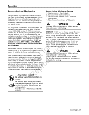
... reverse. The Override will reset to view this potentially dan- 2. Check the Reverse Lockout Mechanism frequently for proper ate blades in yard when mowing. 16 www.snapper.com r n We realize that this new fo tio system. If you operate your previous mowing method but we encourage...for children, pets and hazards before backing machine. To return to "ON" position. STOP BLADES, LOOK AND SEE function. Do not defeat the Reverse Lockout Mechanism. Contact your local Snapper dealer for children, pets and hazards before and while backing. Data indicates that all Rep children...
... reverse. The Override will reset to view this potentially dan- 2. Check the Reverse Lockout Mechanism frequently for proper ate blades in yard when mowing. 16 www.snapper.com r n We realize that this new fo tio system. If you operate your previous mowing method but we encourage...for children, pets and hazards before backing machine. To return to "ON" position. STOP BLADES, LOOK AND SEE function. Do not defeat the Reverse Lockout Mechanism. Contact your local Snapper dealer for children, pets and hazards before and while backing. Data indicates that all Rep children...
Operater's Manual
Page 17
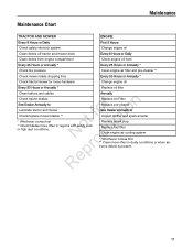
...oil level Every 25 Hours or Annually * Every 25 Hours or Annually * Check tire pressure Clean engine air filter and pre-cleaner ** Check mower blade stopping time Every 50 Hours or Annually * Check tractor/mower for loose hardware Change engine oil Every 50 Hours or Annually * Replace oil filter Clean...airborne debris is present. 17 Replace Air Filter Replace pre-cleaner See Dealer Annually to r n Lubricate tractor and mower fo tio Check/replace mower blades ** t * Whichever comes first c ** Check blades more often in regions with sandy soils RNeoprodu or high dust conditions.
...oil level Every 25 Hours or Annually * Every 25 Hours or Annually * Check tire pressure Clean engine air filter and pre-cleaner ** Check mower blade stopping time Every 50 Hours or Annually * Check tractor/mower for loose hardware Change engine oil Every 50 Hours or Annually * Replace oil filter Clean...airborne debris is present. 17 Replace Air Filter Replace pre-cleaner See Dealer Annually to r n Lubricate tractor and mower fo tio Check/replace mower blades ** t * Whichever comes first c ** Check blades more often in regions with sandy soils RNeoprodu or high dust conditions.
Operater's Manual
Page 18
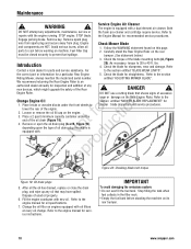
... tank when fuel collects in the filler neck. • Empty the fuel tank before working on its rear bumper. 18 www.snapper.com Engage parking brake. Avoid serious burns, allow all the oil has drained, replace or close the drain plug, and wipe ... 4. Refer Contact a local dealer for a particular Rear Engine 5. Engine Rider. Refer to prevent fuel spillage. 1. Maintenance ! Engine Check Mower Blade and components are HOT. Check the blade for straightness. N d A wear or damage on the rear bumper. (See statement below.) 3. IMPORTANT To avoid damaging the emissions system: &#...
... tank when fuel collects in the filler neck. • Empty the fuel tank before working on its rear bumper. 18 www.snapper.com Engage parking brake. Avoid serious burns, allow all the oil has drained, replace or close the drain plug, and wipe ... 4. Refer Contact a local dealer for a particular Rear Engine 5. Engine Rider. Refer to prevent fuel spillage. 1. Maintenance ! Engine Check Mower Blade and components are HOT. Check the blade for straightness. N d A wear or damage on the rear bumper. (See statement below.) 3. IMPORTANT To avoid damaging the emissions system: &#...
Operater's Manual
Page 19
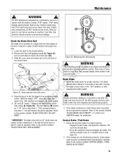
... BELT REPLACEMENT". Lower the deck to the "OFF" position or after the blade has been turned off. If the measurement is 2. Blades must be replaced. SNAPPER dealer for assistance. * IMPORTANT: The blade drive belt on each side of loose parts & tools first. Inspect for proper function. DO NOT attempt any adjustments, maintenance, service or...
... BELT REPLACEMENT". Lower the deck to the "OFF" position or after the blade has been turned off. If the measurement is 2. Blades must be replaced. SNAPPER dealer for assistance. * IMPORTANT: The blade drive belt on each side of loose parts & tools first. Inspect for proper function. DO NOT attempt any adjustments, maintenance, service or...
Operater's Manual
Page 20
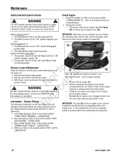
...cover is r not functioning properly. The Clutch/Brake Pedal is in the "ON" (blades engaged) posi- t c 2. With Steps 1 and 2 performed, the shift lever must be completely grease gun. Contact your SNAPPER dealer immediately for inspection. Grease Fittings The following components on the air cleaner cover must...push down to the engine manual for oil specifications. 2. LUBRICATION". 20 www.snapper.com DO NOT attempt to the section entitled "FRONT WHEEL BEARINGS - Change the engine oil. Engine and blades must not start if: 1. Refer to defeat, modify or remove any safety...
...cover is r not functioning properly. The Clutch/Brake Pedal is in the "ON" (blades engaged) posi- t c 2. With Steps 1 and 2 performed, the shift lever must be completely grease gun. Contact your SNAPPER dealer immediately for inspection. Grease Fittings The following components on the air cleaner cover must...push down to the engine manual for oil specifications. 2. LUBRICATION". 20 www.snapper.com DO NOT attempt to the section entitled "FRONT WHEEL BEARINGS - Change the engine oil. Engine and blades must not start if: 1. Refer to defeat, modify or remove any safety...
Operater's Manual
Page 21
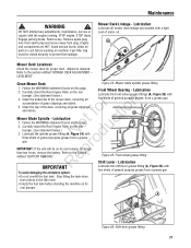
...fuel tank before working on this page. 2. STOP engine. Remove key. Engine and components are HOT. LEVELNESS". Clean Mower Deck Figure 24: Mower blade spindle grease fitting 1. r n 5. Clean the top of the deck, removing all accumulation of motor oil. Refer to the section entitled "MOWER ... ro IMPORTANT: If the unit will be closed securely to cool before standing the machine on its rear bumper for proper level. Mower Blade Spindle - Re IMPORTANT Lubricate the front wheel grease fittings (A, Figure 25) with two shots of general purpose grease, from a grease gun...
...fuel tank before working on this page. 2. STOP engine. Remove key. Engine and components are HOT. LEVELNESS". Clean Mower Deck Figure 24: Mower blade spindle grease fitting 1. r n 5. Clean the top of the deck, removing all accumulation of motor oil. Refer to the section entitled "MOWER ... ro IMPORTANT: If the unit will be closed securely to cool before standing the machine on its rear bumper for proper level. Mower Blade Spindle - Re IMPORTANT Lubricate the front wheel grease fittings (A, Figure 25) with two shots of general purpose grease, from a grease gun...
Operater's Manual
Page 22
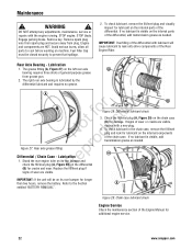
... the fill/level plug (A, Figure 28) on the differential R (B) for lubricant on its rear bumper for additional engine service. 22 www.snapper.com IMPORTANT: If the unit will cause lubricant to prevent fuel spillage. 2. DO NOT attempt any adjustments, maintenance, service or repairs with... signs of general purpose grease from plug. Avoid serious burns, allow all parts to the Section B entitled "BATTERY REMOVAL". WARNING ! STOP blade. The grease fitting (A, Figure 27) on the internal parts of the Rear Engine Rider. Engage parking brake. Remove spark plug wire from ...
... the fill/level plug (A, Figure 28) on the differential R (B) for lubricant on its rear bumper for additional engine service. 22 www.snapper.com IMPORTANT: If the unit will cause lubricant to prevent fuel spillage. 2. DO NOT attempt any adjustments, maintenance, service or repairs with... signs of general purpose grease from plug. Avoid serious burns, allow all parts to the Section B entitled "BATTERY REMOVAL". WARNING ! STOP blade. The grease fitting (A, Figure 27) on the internal parts of the Rear Engine Rider. Engage parking brake. Remove spark plug wire from ...
Operater's Manual
Page 23
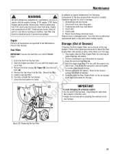
...! Remove the fuel lines from the fuel fo tio filter (A). 4. Install a new fuel filter. Transmission shift lever and detent. 4. Perform all maintenance as required. 3. STOP blade. Carefully reinstall the fuel clamps. 7. Replace worn or damaged parts. grass clippings and debris. 1. Drain the fuel from plug. Remove spark plug wire from spark...
...! Remove the fuel lines from the fuel fo tio filter (A). 4. Install a new fuel filter. Transmission shift lever and detent. 4. Perform all maintenance as required. 3. STOP blade. Carefully reinstall the fuel clamps. 7. Replace worn or damaged parts. grass clippings and debris. 1. Drain the fuel from plug. Remove spark plug wire from spark...
Operater's Manual
Page 24
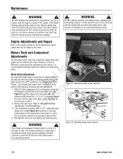
...rotate the brake adjustment nut (A, Figure 32) clockwise to an authorized Snapper dealer. Refer to decrease brake tension. 4. If the dimension is incorrect go to 3-1/4" clearance between the front of the blade lever (A, r Figure 31) and the edge of the plate. DO... NOT attempt any time the blades are HOT. Remove key. Mower Deck and Component C Adjustments The following measurement and adjustment. 1. Once blade is not operating properly. Figure 32: Adjusting blade brake tension 24 www.snapper.com STOP engine. With the blade engagement lever disengaged, measure o...
...rotate the brake adjustment nut (A, Figure 32) clockwise to an authorized Snapper dealer. Refer to decrease brake tension. 4. If the dimension is incorrect go to 3-1/4" clearance between the front of the blade lever (A, r Figure 31) and the edge of the plate. DO... NOT attempt any time the blades are HOT. Remove key. Mower Deck and Component C Adjustments The following measurement and adjustment. 1. Once blade is not operating properly. Figure 32: Adjusting blade brake tension 24 www.snapper.com STOP engine. With the blade engagement lever disengaged, measure o...


