

Instruction Manual
Page 5
...in the course of engine damage due to the assembly stand. do not use original STIHL replacement parts. Always wear suitable protective gloves for operations in which occur can be performed outdoors only. Coat the ends of the fuel system. replace as the safety precautions ...guide bar before re-installing - Check disassembled parts for wear or damage before carrying out repairs or mounting the machine to overheating. 4 MS 231, MS 231 C, MS 251, MS 251 C Do not re-use fuel hoses after working on the ignition system. They can be identified by hand, to the hose barbs...
...in the course of engine damage due to the assembly stand. do not use original STIHL replacement parts. Always wear suitable protective gloves for operations in which occur can be performed outdoors only. Coat the ends of the fuel system. replace as the safety precautions ...guide bar before re-installing - Check disassembled parts for wear or damage before carrying out repairs or mounting the machine to overheating. 4 MS 231, MS 231 C, MS 251, MS 251 C Do not re-use fuel hoses after working on the ignition system. They can be identified by hand, to the hose barbs...

Instruction Manual
Page 34
... air to part or full throttle is in castings are the usual causes of the prescribed idle speed difficult, if not impossible. Always perform the vacuum test first and then the pressure test. Moreover, the transition from idle speed to enter the engine and upset the fuel-....25 mm c = 6 mm - 2310RA072 TG 2310RA074 TG 6.2 Leakage Test Defective oil seals and gaskets or cracks in place. 2310RA079 TG a 2710RA164 TG 2310RA073 TG MS 231, MS 231 C, MS 251, MS 251 C 33 Remove the shroud, b 6.4 c 1 1 b - Set the piston to top dead center. The engine can be modified as shown.
... air to part or full throttle is in castings are the usual causes of the prescribed idle speed difficult, if not impossible. Always perform the vacuum test first and then the pressure test. Moreover, the transition from idle speed to enter the engine and upset the fuel-....25 mm c = 6 mm - 2310RA072 TG 2310RA074 TG 6.2 Leakage Test Defective oil seals and gaskets or cracks in place. 2310RA079 TG a 2710RA164 TG 2310RA073 TG MS 231, MS 231 C, MS 251, MS 251 C 33 Remove the shroud, b 6.4 c 1 1 b - Set the piston to top dead center. The engine can be modified as shown.

Instruction Manual
Page 39
...1 2310RA093 TG 2310RA096 TG 2310RA087 TG : Carefully swing the engine (1) in 1 the direction of the clutch and lift it away. 38 MS 231, MS 231 C, MS 251, MS 251 C do not tighten them down . Loosen and remove the engine pan, remove remaining sealant and clean the sealing faces, b 14 Installing .... 1 2310RA427 TG 2310RA092 TG 2310RA098 TG - After loosening the engine pan, always clean the sealing faces and apply fresh sealant, b 14. - Perform leakage test, b 6.2 6.6 Cylinder / Crankshaft - the bores in the engine housing, engine pan and cylinder must be in alignment. : Push the...
...1 2310RA093 TG 2310RA096 TG 2310RA087 TG : Carefully swing the engine (1) in 1 the direction of the clutch and lift it away. 38 MS 231, MS 231 C, MS 251, MS 251 C do not tighten them down . Loosen and remove the engine pan, remove remaining sealant and clean the sealing faces, b 14 Installing .... 1 2310RA427 TG 2310RA092 TG 2310RA098 TG - After loosening the engine pan, always clean the sealing faces and apply fresh sealant, b 14. - Perform leakage test, b 6.2 6.6 Cylinder / Crankshaft - the bores in the engine housing, engine pan and cylinder must be in alignment. : Push the...

Instruction Manual
Page 51
... reverse sequence. 7.7.2 Removing and Installing - Pull the carburetor towards the control handle - carefully out of the guides (arrows) in the air guide shroud. 50 MS 231, MS 231 C, MS 251, MS 251 C Set the Master Control lever to stretch the fuel hose. - Remove the shroud, b 6.4 - Remove the choke rod, b 10.3.3 1 - If it is much ... of the troubleshooting chart, b 7.8 - Set the Master Control lever to "0". 2310RA131 TG The resistance measured must be infinitely high. Remove the fan housing, b 8.2 1 2 Also perform contact and continuity check on the filter base, b 10.1 -
... reverse sequence. 7.7.2 Removing and Installing - Pull the carburetor towards the control handle - carefully out of the guides (arrows) in the air guide shroud. 50 MS 231, MS 231 C, MS 251, MS 251 C Set the Master Control lever to stretch the fuel hose. - Remove the shroud, b 6.4 - Remove the choke rod, b 10.3.3 1 - If it is much ... of the troubleshooting chart, b 7.8 - Set the Master Control lever to "0". 2310RA131 TG The resistance measured must be infinitely high. Remove the fan housing, b 8.2 1 2 Also perform contact and continuity check on the filter base, b 10.1 -

Instruction Manual
Page 54
Check operation of switch lever, b 10.1 - Reassemble all other parts in the contact spring's loop, perform contact and continuity test if necessary, b 7.7.1. - Check the contact spring and replace it over the tab (arrow). : Ease the contact spring (1) out ... 890 4000 to one side. - Pull the filter base off the studs, b 12.3 : Lift the contact spring (1) a little and ease it if necessary, MS 231, MS 231 C, MS 251, MS 251 C 53 7.7.3 Ground Wire 1 3 Test and install the ground wire as described for contact and continuity 2 and 2 replace the wiring harness if necessary, b 7.7...
Check operation of switch lever, b 10.1 - Reassemble all other parts in the contact spring's loop, perform contact and continuity test if necessary, b 7.7.1. - Check the contact spring and replace it over the tab (arrow). : Ease the contact spring (1) out ... 890 4000 to one side. - Pull the filter base off the studs, b 12.3 : Lift the contact spring (1) a little and ease it if necessary, MS 231, MS 231 C, MS 251, MS 251 C 53 7.7.3 Ground Wire 1 3 Test and install the ground wire as described for contact and continuity 2 and 2 replace the wiring harness if necessary, b 7.7...

Instruction Manual
Page 95
Carry out the basic setting, b 12.7.1 94 MS 231, MS 231 C, MS 251, MS 251 C 1 1 Pre-installing limiter cap 1 2310RA279 TG 2310RA277 TG 2310RA281 TG : Screw the puller (1) 5910 890 4502 about 5 turns counterclockwise into the limiter cap - Always install a ... cap (1) on to the high speed screw (H) as far as stop. : Pull out the limiter cap (1). - do not push fully home. The basic setting is performed through the pre-installed limiter cap with screwdriver 5910 890 2306. - the high speed screw (H) may otherwise be damaged. 1 1 2310RA278 TG : Screw down the high...
Carry out the basic setting, b 12.7.1 94 MS 231, MS 231 C, MS 251, MS 251 C 1 1 Pre-installing limiter cap 1 2310RA279 TG 2310RA277 TG 2310RA281 TG : Screw the puller (1) 5910 890 4502 about 5 turns counterclockwise into the limiter cap - Always install a ... cap (1) on to the high speed screw (H) as far as stop. : Pull out the limiter cap (1). - do not push fully home. The basic setting is performed through the pre-installed limiter cap with screwdriver 5910 890 2306. - the high speed screw (H) may otherwise be damaged. 1 1 2310RA278 TG : Screw down the high...
Instruction Manual
Page 97
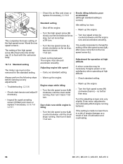
... if necessary, b 12.1 Standard setting - Warm up the engine. - Even minor adjustments can noticeably affect engine running , then turn it back 1 full turn . Always perform the following steps before carrying out any adjustments: - Troubleshooting, b 3.6 - Inspect the spark arresting screen (if fitted) and clean or replace if necessary, b 3.7 or ... idling behavior, poor acceleration (although standard setting is idling - Warm up the engine. - It is a risk of lubrication and overheating. 96 MS 231, MS 231 C, MS 251, MS 251 C Turn the adjusting screws only very slightly.
... if necessary, b 12.1 Standard setting - Warm up the engine. - Even minor adjustments can noticeably affect engine running , then turn it back 1 full turn . Always perform the following steps before carrying out any adjustments: - Troubleshooting, b 3.6 - Inspect the spark arresting screen (if fitted) and clean or replace if necessary, b 3.7 or ... idling behavior, poor acceleration (although standard setting is idling - Warm up the engine. - It is a risk of lubrication and overheating. 96 MS 231, MS 231 C, MS 251, MS 251 C Turn the adjusting screws only very slightly.

Instruction Manual
Page 100
...drain the fuel tank, b 1. - There must be no buildup of pressure takes place via the fuel hose. - Remove the carburetor, b 12.5 MS 231, MS 231 C, MS 251, MS 251 C 99 Reassemble all other parts in the fuel tank. - create a vacuum in the fuel tank. If necessary, install a new tank vent or fuel... ring (1) to the left and connect the pump (2) 0000 850 1300 to the nipple (arrow) - Close the tank cap. - Check function by performing pressure and vacuum tests on the carburetor or the fuel supply system, also check and clean the tank vent and replace it if necessary. Installing...
...drain the fuel tank, b 1. - There must be no buildup of pressure takes place via the fuel hose. - Remove the carburetor, b 12.5 MS 231, MS 231 C, MS 251, MS 251 C 99 Reassemble all other parts in the fuel tank. - create a vacuum in the fuel tank. If necessary, install a new tank vent or fuel... ring (1) to the left and connect the pump (2) 0000 850 1300 to the nipple (arrow) - Close the tank cap. - Check function by performing pressure and vacuum tests on the carburetor or the fuel supply system, also check and clean the tank vent and replace it if necessary. Installing...