
Instruction Manual
Page 2
... AV Spring on Fuel Tank 66 AV Spring on Handlebar 67 Stop Buffers 68 Buffers on Machines with Manual Fuel Pump 85 12.5 Carburetor 88 12.5.1 Leakage Test 89 RA_737_00_01_01 MS 231, MS 231 C, MS 251, MS 251 C q © ANDREAS STIHL AG & Co. QuickStop Super 73 10.3.1 Switch Lever QuickStop Super 74 10.3.2 Lockout Lever - Chain Lubrication 78...
... AV Spring on Fuel Tank 66 AV Spring on Handlebar 67 Stop Buffers 68 Buffers on Machines with Manual Fuel Pump 85 12.5 Carburetor 88 12.5.1 Leakage Test 89 RA_737_00_01_01 MS 231, MS 231 C, MS 251, MS 251 C q © ANDREAS STIHL AG & Co. QuickStop Super 73 10.3.1 Switch Lever QuickStop Super 74 10.3.2 Lockout Lever - Chain Lubrication 78...

Instruction Manual
Page 3
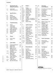
Servicing Aids 112 2 MS 231, MS 231 C, MS 251, MS 251 C Contents 12.6 Servicing the Carburetor 90 12.6.1 Metering Diaphragm 90 12.6.2 Inlet Needle 90 12.6.3 Pump Diaphragm 91 12.6.4 Lever on Throttle Shaft 92 12.6.5 ... 100 12.11 Fuel Intake 101 12.11.1 Pickup Body 101 12.11.2 Fuel Hose 101 12.11.3 Fuel Hoses - Special Servicing Tools 110 14. Manual Fuel Pump 105 12.11.4 Manual Fuel Pump 107 12.11.5 Tank Housing 108 13.
Servicing Aids 112 2 MS 231, MS 231 C, MS 251, MS 251 C Contents 12.6 Servicing the Carburetor 90 12.6.1 Metering Diaphragm 90 12.6.2 Inlet Needle 90 12.6.3 Pump Diaphragm 91 12.6.4 Lever on Throttle Shaft 92 12.6.5 ... 100 12.11 Fuel Intake 101 12.11.1 Pickup Body 101 12.11.2 Fuel Hose 101 12.11.3 Fuel Hoses - Special Servicing Tools 110 14. Manual Fuel Pump 105 12.11.4 Manual Fuel Pump 107 12.11.5 Tank Housing 108 13.

Instruction Manual
Page 4
... individual components and assemblies. Technical information bulletins also supplement the parts list until a revised edition is held in position. Service manuals and all special servicing tools currently available from STIHL. MS 231, MS 231 C, MS 251, MS 251 C 3 They show the installed positions of properly equipped repair shops. A fault on the machine may damage housings when the machine...
... individual components and assemblies. Technical information bulletins also supplement the parts list until a revised edition is held in position. Service manuals and all special servicing tools currently available from STIHL. MS 231, MS 231 C, MS 251, MS 251 C 3 They show the installed positions of properly equipped repair shops. A fault on the machine may damage housings when the machine...

Instruction Manual
Page 5
...injuries. Always wear suitable protective gloves for operations in which occur can be explosive in this service manual. The chapter on tightening torques lists all local and countryspecific safety regulations as well as necessary. Fuel system - ...MS 231 C, MS 251, MS 251 C fuel hoses can be maintained when tightening down screws, nuts and other source of the fuel system. Always install new hoses - Improper handling may appear alone on the fuel system and the engine. They can be performed outdoors only. All work with the connector, preferably by the STIHL...
...injuries. Always wear suitable protective gloves for operations in which occur can be explosive in this service manual. The chapter on tightening torques lists all local and countryspecific safety regulations as well as necessary. Fuel system - ...MS 231 C, MS 251, MS 251 C fuel hoses can be maintained when tightening down screws, nuts and other source of the fuel system. Always install new hoses - Improper handling may appear alone on the fuel system and the engine. They can be performed outdoors only. All work with the connector, preferably by the STIHL...
Instruction Manual
Page 6
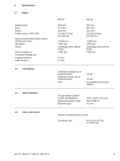
... mm 30.0 mm 2.0 kW (2.7 bhp) at 9,500 rpm 13,000 rpm 2,800 rpm Centrifugal clutch without linings 3,500 rpm 0.5 bar 0.5 bar MS 251 45.6 cm3 44.0 mm 30.0 mm 2.2 kW (3.0 bhp) at 9,500 rpm 13,000 rpm 2,800 rpm Centrifugal clutch without linings 3,500 rpm Carburetor...gauge pressure: Fuel: 0.8 bar 0.5 bar as specified in instruction manual Air gap between ignition module and fanwheel: Spark plug (resistor type): Electrode gap: 0.30 (+ 0.05/- 0.10) mm NGK CMR 6 H 0.5 mm Speed-controlled Ematic oil pump Oil delivery rate: 8.0 (+/3.0) cm3/min at 10,000 rpm MS 231, MS 231 C, MS 251, MS 251 C 5
... mm 30.0 mm 2.0 kW (2.7 bhp) at 9,500 rpm 13,000 rpm 2,800 rpm Centrifugal clutch without linings 3,500 rpm 0.5 bar 0.5 bar MS 251 45.6 cm3 44.0 mm 30.0 mm 2.2 kW (3.0 bhp) at 9,500 rpm 13,000 rpm 2,800 rpm Centrifugal clutch without linings 3,500 rpm Carburetor...gauge pressure: Fuel: 0.8 bar 0.5 bar as specified in instruction manual Air gap between ignition module and fanwheel: Spark plug (resistor type): Electrode gap: 0.30 (+ 0.05/- 0.10) mm NGK CMR 6 H 0.5 mm Speed-controlled Ematic oil pump Oil delivery rate: 8.0 (+/3.0) cm3/min at 10,000 rpm MS 231, MS 231 C, MS 251, MS 251 C 5

Instruction Manual
Page 20
... thickness. left-hand thread. - Remove the shroud, b 6.4 : The locking strip (1) 0000 893 5904 must rest on the piston crown - MS 231, MS 231 C, MS 251, MS 251 C 19 Remove and install the clutch drum, see instruction manual. - Install the clutch drum. : Hold the locking strip (1) 0000 893 5904 so that the word "TOP" faces outwards. : Position the...
... thickness. left-hand thread. - Remove the shroud, b 6.4 : The locking strip (1) 0000 893 5904 must rest on the piston crown - MS 231, MS 231 C, MS 251, MS 251 C 19 Remove and install the clutch drum, see instruction manual. - Install the clutch drum. : Hold the locking strip (1) 0000 893 5904 so that the word "TOP" faces outwards. : Position the...
Instruction Manual
Page 21
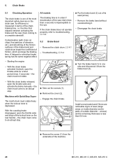
...outside diameter - Contamination (with QuickStop Super - Troubleshooting, b 3.2 - With the chain brake activated (locked), open the throttle wide and activate the brake manually - With the chain brake released, open the throttle wide for a brief 1 TOP period (max. 3 seconds) - the chain must not rotate. :... etc.) and smoothing of the friction surfaces of the brake band and clutch drum impair the coefficient of the machine. 20 MS 231, MS 231 C, MS 251, MS 251 C the time that elapses between activating the brake and the saw . The braking time is depressed. Remove the clutch drum,...
...outside diameter - Contamination (with QuickStop Super - Troubleshooting, b 3.2 - With the chain brake activated (locked), open the throttle wide and activate the brake manually - With the chain brake released, open the throttle wide for a brief 1 TOP period (max. 3 seconds) - the chain must not rotate. :... etc.) and smoothing of the friction surfaces of the brake band and clutch drum impair the coefficient of the machine. 20 MS 231, MS 231 C, MS 251, MS 251 C the time that elapses between activating the brake and the saw . The braking time is depressed. Remove the clutch drum,...

Instruction Manual
Page 29
... fuel hose (3) or, on versions with a manual fuel pump, to the right of the fuel hose (3) and fuel return hose (2). : Push the brake cable (1), short hook (4) first, through the bore (arrow) in the engine housing. 1 2 : Push the insert (1) with the housing ribs. 28 MS 231, MS 231 C, MS 251, MS 251 C The insert must be flush with...
... fuel hose (3) or, on versions with a manual fuel pump, to the right of the fuel hose (3) and fuel return hose (2). : Push the brake cable (1), short hook (4) first, through the bore (arrow) in the engine housing. 1 2 : Push the insert (1) with the housing ribs. 28 MS 231, MS 231 C, MS 251, MS 251 C The insert must be flush with...
Instruction Manual
Page 33
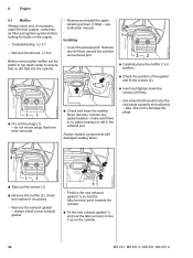
6. Troubleshooting, b 3.7 - see instruction manual. do not re-use the tabs (arrows) to push home the new plugs squarely and uniformly - make sure there is no dirt falls into the ... 6.1 Muffler Always check and, if necessary, repair the fuel system, carburetor, air filter and ignition system before looking for faults on the cylinder. 32 MS 231, MS 231 C, MS 251, MS 251 C Always replace components with damaged sealing faces. 2 2310RA068 TG 2310RA070 TG 11 : Take out the screws (1). : Remove the muffler (2), check and replace if necessary...
6. Troubleshooting, b 3.7 - see instruction manual. do not re-use the tabs (arrows) to push home the new plugs squarely and uniformly - make sure there is no dirt falls into the ... 6.1 Muffler Always check and, if necessary, repair the fuel system, carburetor, air filter and ignition system before looking for faults on the cylinder. 32 MS 231, MS 231 C, MS 251, MS 251 C Always replace components with damaged sealing faces. 2 2310RA068 TG 2310RA070 TG 11 : Take out the screws (1). : Remove the muffler (2), check and replace if necessary...

Instruction Manual
Page 72
... carburetor box. - Remove the short circuit wire from the switch lever, b 7.7.2 : Remove the switch lever (1), check it if necessary lever are described in the instruction manual. Check the filter base and replace 2 The positions of the Master Control it and replace if necessary. Fit the short circuit wire on the 1 switch... short circuit wire points towards the filter base and the opening (arrow) lines up with the web (2). 1 2310RA161 TG - Reassemble all other parts in position "0". - MS 231, MS 231 C, MS 251, MS 251 C 71
... carburetor box. - Remove the short circuit wire from the switch lever, b 7.7.2 : Remove the switch lever (1), check it if necessary lever are described in the instruction manual. Check the filter base and replace 2 The positions of the Master Control it and replace if necessary. Fit the short circuit wire on the 1 switch... short circuit wire points towards the filter base and the opening (arrow) lines up with the web (2). 1 2310RA161 TG - Reassemble all other parts in position "0". - MS 231, MS 231 C, MS 251, MS 251 C 71

Instruction Manual
Page 78
... replace if necessary Installing 2 : Push the carburetor (1) with manual fuel pump 1 - All models - Reassemble all other parts in the carburetor carrier until it snaps into position. - Install the throttle trigger, b 10.2 1 1 2310RA294 TG 2310RA297 TG 2310RA199 TG : Remove the fuel hose (1). MS 231, MS 231 C, MS 251, MS 251 C 77 All models 1 : Pass the throttle cable (1) through...
... replace if necessary Installing 2 : Push the carburetor (1) with manual fuel pump 1 - All models - Reassemble all other parts in the carburetor carrier until it snaps into position. - Install the throttle trigger, b 10.2 1 1 2310RA294 TG 2310RA297 TG 2310RA199 TG : Remove the fuel hose (1). MS 231, MS 231 C, MS 251, MS 251 C 77 All models 1 : Pass the throttle cable (1) through...

Instruction Manual
Page 82
...2 : Pry the filter base (1) out of the buffer (2). 2310RA195 TG : Pull the short circuit wire (1) and ground wire (2) out of the buffer (2). - MS 231, MS 231 C, MS 251, MS 251 C 81 2310RA198 TG 12. Fuel System 12.1 Air Filter 12.2 Baffle Dirty air filters reduce engine power, increase fuel consumption and make starting more... the shroud, b 6.4 1 : Pull the filter base (1) off the studs (arrows). 2310RA313 TG 1 : Unscrew the nuts (arrows). 1 : Remove the baffle (1). 2310RA312 TG - see instruction manual. - Reassemble in the reverse sequence. - Remove the choke rod, b 10.3.3 -
...2 : Pry the filter base (1) out of the buffer (2). 2310RA195 TG : Pull the short circuit wire (1) and ground wire (2) out of the buffer (2). - MS 231, MS 231 C, MS 251, MS 251 C 81 2310RA198 TG 12. Fuel System 12.1 Air Filter 12.2 Baffle Dirty air filters reduce engine power, increase fuel consumption and make starting more... the shroud, b 6.4 1 : Pull the filter base (1) off the studs (arrows). 2310RA313 TG 1 : Unscrew the nuts (arrows). 1 : Remove the baffle (1). 2310RA312 TG - see instruction manual. - Reassemble in the reverse sequence. - Remove the choke rod, b 10.3.3 -

Instruction Manual
Page 86
... guide shroud (2) in the direction of the guides (arrows). : Ease the air guide shroud (1) over the stop (arrow) and lift it to one side with Manual Fuel 2 Pump 1 - 12.4.1 Air Guide Shroud - Remove the carburetor, b 12.5 - Pull the filter base off the spark plug. : Take out the ..., b 10.3.4 : Pull the fuel return hose (1) out of the cylinder and pull the air guide shroud away at the same time. 2310RA338 TG MS 231, MS 231 C, MS 251, MS 251 C 85 Models with the wiring harness still attached, b 12.3 - Remove the fan housing, b 8.2 3 - Put the wiring harness with filter ...
... guide shroud (2) in the direction of the guides (arrows). : Ease the air guide shroud (1) over the stop (arrow) and lift it to one side with Manual Fuel 2 Pump 1 - 12.4.1 Air Guide Shroud - Remove the carburetor, b 12.5 - Pull the filter base off the spark plug. : Take out the ..., b 10.3.4 : Pull the fuel return hose (1) out of the cylinder and pull the air guide shroud away at the same time. 2310RA338 TG MS 231, MS 231 C, MS 251, MS 251 C 85 Models with the wiring harness still attached, b 12.3 - Remove the fan housing, b 8.2 3 - Put the wiring harness with filter ...

Instruction Manual
Page 89
... with manual fuel pump - Open the fuel tank cap and drain the fuel tank. Install new fuel intake hose, b 12.11.3 Installing 1 Make sure the washer (1) is in place. - Make sure sealing ring (2) is in manifold flange. - Install a new fuel hose, b 12.11.2 2310RA353 TG 88 MS 231, MS 231 C, MS 251, MS 251 C ...circuit wire (2) and ground wire (3) into its seat until it is open. : Remove the carburetor (1). Stub (3) must engage bore in place. Models with manual fuel pump 1 - 2310RA286 TG 2 1 3 1 2310RA350 TG : Push the rubber grommet (1) into the guides (arrows) -
... with manual fuel pump - Open the fuel tank cap and drain the fuel tank. Install new fuel intake hose, b 12.11.3 Installing 1 Make sure the washer (1) is in place. - Make sure sealing ring (2) is in manifold flange. - Install a new fuel hose, b 12.11.2 2310RA353 TG 88 MS 231, MS 231 C, MS 251, MS 251 C ...circuit wire (2) and ground wire (3) into its seat until it is open. : Remove the carburetor (1). Stub (3) must engage bore in place. Models with manual fuel pump 1 - 2310RA286 TG 2 1 3 1 2310RA350 TG : Push the rubber grommet (1) into the guides (arrows) -

Instruction Manual
Page 90
... to the nipple (2) 0000 855 9200. : Push the fuel hose with manual fuel pump 1 : Push the new fuel hose (1) onto the nipples (arrows). 2310RA356 TG 2310RA355 TG 2310RA354 TG 2310RA255 TG - Reassemble all other parts in the - MS 231, MS 231 C, MS 251, MS 251 C 89 Set throttle trigger to full throttle position, the throttle shutter must...
... to the nipple (2) 0000 855 9200. : Push the fuel hose with manual fuel pump 1 : Push the new fuel hose (1) onto the nipples (arrows). 2310RA356 TG 2310RA355 TG 2310RA354 TG 2310RA255 TG - Reassemble all other parts in the - MS 231, MS 231 C, MS 251, MS 251 C 89 Set throttle trigger to full throttle position, the throttle shutter must...

Instruction Manual
Page 91
...damage the Oring (arrow). - Check position of fatigue. Install a new gasket. Reassemble all other parts in the tabs. 90 MS 231, MS 231 C, MS 251, MS 251 C Check the metering diaphragm for signs of the choke shutter and the holes line up. : Fit the screws (2) but ... i.e. Remove the metering diaphragm, b 12.6.1 2310RA257 TG 2310RA259 TG 1 : Check the O-ring (1) and replace it if necessary : On versions with a manual fuel pump, check the nipple (2) and replace the end cover if necessary. - Note installed positions of metering diaphragm (2) and gasket (1). : Position the gasket...
...damage the Oring (arrow). - Check position of fatigue. Install a new gasket. Reassemble all other parts in the tabs. 90 MS 231, MS 231 C, MS 251, MS 251 C Check the metering diaphragm for signs of the choke shutter and the holes line up. : Fit the screws (2) but ... i.e. Remove the metering diaphragm, b 12.6.1 2310RA257 TG 2310RA259 TG 1 : Check the O-ring (1) and replace it if necessary : On versions with a manual fuel pump, check the nipple (2) and replace the end cover if necessary. - Note installed positions of metering diaphragm (2) and gasket (1). : Position the gasket...

Instruction Manual
Page 99
... 2310RA358 TG A damaged intake manifold can result in the intake manifold (1) must be clear, clean if necessary - Always replace components with manual fuel pump, b 12.4.1 : Inspect and clean the sealing faces (arrows), b 14 The sealing faces must be in perfect condition. Remove... into position. 1 : Take out the screws (arrows). : Remove the intake manifold (1). 1 The bore (1) in the reverse sequence. 98 MS 231, MS 231 C, MS 251, MS 251 C Remove the air guide shroud, b 12.4 Models with damaged sealing faces. 2310RA287 TG 2 1 2310RA359 TG 2310RA357 TG : Push the throttle...
... 2310RA358 TG A damaged intake manifold can result in the intake manifold (1) must be clear, clean if necessary - Always replace components with manual fuel pump, b 12.4.1 : Inspect and clean the sealing faces (arrows), b 14 The sealing faces must be in perfect condition. Remove... into position. 1 : Take out the screws (arrows). : Remove the intake manifold (1). 1 The bore (1) in the reverse sequence. 98 MS 231, MS 231 C, MS 251, MS 251 C Remove the air guide shroud, b 12.4 Models with damaged sealing faces. 2310RA287 TG 2 1 2310RA359 TG 2310RA357 TG : Push the throttle...

Instruction Manual
Page 100
... or the fuel supply system, also check and clean the tank vent and replace it if necessary. Install the air guide shroud, b 12.4 Models with manual fuel pump 1 2 : Use a suitable plug (2) to seal the fuel suction hose (1). 2310RA362 TG 1 : Push the ring (1) to the left and connect the.... : Insert the screws (arrows) and tighten them down firmly. - Equalization of vacuum in the fuel tank. - Remove the carburetor, b 12.5 MS 231, MS 231 C, MS 251, MS 251 C 99 There must be no buildup of pressure takes place via the fuel hose. - Clean the area around the tank vent. - Check function by...
... or the fuel supply system, also check and clean the tank vent and replace it if necessary. Install the air guide shroud, b 12.4 Models with manual fuel pump 1 2 : Use a suitable plug (2) to seal the fuel suction hose (1). 2310RA362 TG 1 : Push the ring (1) to the left and connect the.... : Insert the screws (arrows) and tighten them down firmly. - Equalization of vacuum in the fuel tank. - Remove the carburetor, b 12.5 MS 231, MS 231 C, MS 251, MS 251 C 99 There must be no buildup of pressure takes place via the fuel hose. - Clean the area around the tank vent. - Check function by...

Instruction Manual
Page 102
Open the tank again and drain it and replace if necessary. 1 : Take out the screw (1). In the event of problems with manual fuel pump, b 12.4.1 2310RA374 TG MS 231, MS 231 C, MS 251, MS 251 C 101 Pour a small amount of the filter eventually become clogged with the fuel are retained by the pickup body (filter). Remove the carburetor...
Open the tank again and drain it and replace if necessary. 1 : Take out the screw (1). In the event of problems with manual fuel pump, b 12.4.1 2310RA374 TG MS 231, MS 231 C, MS 251, MS 251 C 101 Pour a small amount of the filter eventually become clogged with the fuel are retained by the pickup body (filter). Remove the carburetor...

Instruction Manual
Page 105
... the tank housing (2). - Insert screw and tighten it in the guide (arrow). - Check position of fuel hose and correct if necessary, b 12.11.2 - Machines with manual fuel pump, b 12.4.1 - Insert the screws and tighten them down firmly. : Use hook 5910 893 8800 to remove the fuel suction hose (1) from the fuel.... : Insert and tighten down the screw (2) firmly. : Ease the handlebar (1) sideways and place it down firmly. : Fit the AV spring (1) in the reverse sequence. 104 MS 231, MS 231 C, MS 251, MS 251 C
... the tank housing (2). - Insert screw and tighten it in the guide (arrow). - Check position of fuel hose and correct if necessary, b 12.11.2 - Machines with manual fuel pump, b 12.4.1 - Insert the screws and tighten them down firmly. : Use hook 5910 893 8800 to remove the fuel suction hose (1) from the fuel.... : Insert and tighten down the screw (2) firmly. : Ease the handlebar (1) sideways and place it down firmly. : Fit the AV spring (1) in the reverse sequence. 104 MS 231, MS 231 C, MS 251, MS 251 C


