
User's Guide
Page 2
... ...8 Rear Panel Components ...9 INSTALLING THE CAMERA...11 Attach Camera to Stand...11 Connect Ethernet Cable ...12 Connect Power using AC Adapter and Power on Camera 12 Reset Camera...13 SETUPWIZARD...14 USING THE CAMERA WEB MANAGER 31 Accessing the Camera Video Display ...31 Login...32 Web Manager...Audio ...47 Action ...49 Motion Detection...53 Tools...53 Device Info ...54 IPVIEW PRO 2.0 ...56 IPView Pro 2.0 User Interface ...59 Camera configuration with IPView Pro 2.0 62 Schedule Recording with IPView Pro 2.0 ...64 Setup Motion Detection and Digital Input with IPView Pro 2.0 66 ...
... ...8 Rear Panel Components ...9 INSTALLING THE CAMERA...11 Attach Camera to Stand...11 Connect Ethernet Cable ...12 Connect Power using AC Adapter and Power on Camera 12 Reset Camera...13 SETUPWIZARD...14 USING THE CAMERA WEB MANAGER 31 Accessing the Camera Video Display ...31 Login...32 Web Manager...Audio ...47 Action ...49 Motion Detection...53 Tools...53 Device Info ...54 IPVIEW PRO 2.0 ...56 IPView Pro 2.0 User Interface ...59 Camera configuration with IPView Pro 2.0 62 Schedule Recording with IPView Pro 2.0 ...64 Setup Motion Detection and Digital Input with IPView Pro 2.0 66 ...

User's Guide
Page 4
... One Metal Mounting Plate • 2x M3 6mm Screws for screwing the Camera to the Metal Plate • 2x M3 16mm Screws for mounting the Camera to install the TV‐IP602WN ProView Wireless N Pan/Tilt Internet Camera and use it for proper installation of the above items are accessible through... that you understand all the necessary information and equipment on how to a wall or ceiling If any of your reseller. TV‐IP602WN ProView Wireless N Pan/Tilt Internet Camera About This User's Guide This User Guide provides instructions on hand before beginning the installation.
... One Metal Mounting Plate • 2x M3 6mm Screws for screwing the Camera to the Metal Plate • 2x M3 16mm Screws for mounting the Camera to install the TV‐IP602WN ProView Wireless N Pan/Tilt Internet Camera and use it for proper installation of the above items are accessible through... that you understand all the necessary information and equipment on how to a wall or ceiling If any of your reseller. TV‐IP602WN ProView Wireless N Pan/Tilt Internet Camera About This User's Guide This User Guide provides instructions on hand before beginning the installation.

User's Guide
Page 5
... Area Network: IEEE 802.11b/g/n Wireless LAN v TV‐IP602WN ProView Wireless N Pan/Tilt Internet Camera System Requirements Computer • CPU: P4 2.8GHz or above • Memory: 1G or above (4GB recommended if monitoring more than one camera) • VGA Resolution: 1024 x 768 or above...• IPView Pro 2.0 Application Users must use a high performance system, such as a Pentium 4 2.8GHz PC. Note: When you connect multiple cameras and monitor their images synchronously, it is recommended to use Microsoft® Windows® XP, Vista, and 7 Operating System with: o Internet Explorer...
... Area Network: IEEE 802.11b/g/n Wireless LAN v TV‐IP602WN ProView Wireless N Pan/Tilt Internet Camera System Requirements Computer • CPU: P4 2.8GHz or above • Memory: 1G or above (4GB recommended if monitoring more than one camera) • VGA Resolution: 1024 x 768 or above...• IPView Pro 2.0 Application Users must use a high performance system, such as a Pentium 4 2.8GHz PC. Note: When you connect multiple cameras and monitor their images synchronously, it is recommended to use Microsoft® Windows® XP, Vista, and 7 Operating System with: o Internet Explorer...

User's Guide
Page 6
... is 192.168.10.30. (Make sure your Web browser to access the camera monitor screen and configuration menus using a Web browser. vi TV‐IP602WN ProView Wireless N Pan/Tilt Internet Camera Default Settings Use the default settings to enter when you will enter into the Address... field of the camera.) Subnet Mask The default subnet mask is 255.255.255.0. ...
... is 192.168.10.30. (Make sure your Web browser to access the camera monitor screen and configuration menus using a Web browser. vi TV‐IP602WN ProView Wireless N Pan/Tilt Internet Camera Default Settings Use the default settings to enter when you will enter into the Address... field of the camera.) Subnet Mask The default subnet mask is 255.255.255.0. ...

User's Guide
Page 7
... and web‐based solution that move through a selected area of transmitting real‐time high‐quality video images for monitoring. TV‐IP602WN ProView Wireless N Pan/Tilt Internet Camera 1 Introduction The TV‐IP602WN ProView Wireless N Pan/Tilt Internet Camera is available, you can also upgrade remotely over an intranet or the Internet. The...
... and web‐based solution that move through a selected area of transmitting real‐time high‐quality video images for monitoring. TV‐IP602WN ProView Wireless N Pan/Tilt Internet Camera 1 Introduction The TV‐IP602WN ProView Wireless N Pan/Tilt Internet Camera is available, you can also upgrade remotely over an intranet or the Internet. The...

User's Guide
Page 8
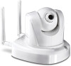
... powered off. 8 The LED will blink 0.5 times per second if the WPS connection has failed. TV‐IP602WN ProView Wireless N Pan/Tilt Internet Camera Camera Hardware Components Below is a summary description of the camera hardware: Front Panel Components Adjustable focus camera lens Audio mic Link LED indicator Power LED indicator LED Indicators LNK PWR Front panel...
... powered off. 8 The LED will blink 0.5 times per second if the WPS connection has failed. TV‐IP602WN ProView Wireless N Pan/Tilt Internet Camera Camera Hardware Components Below is a summary description of the camera hardware: Front Panel Components Adjustable focus camera lens Audio mic Link LED indicator Power LED indicator LED Indicators LNK PWR Front panel...
User's Guide
Page 9
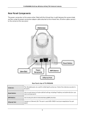
... the rear panel. The port is split between the camera body and lens using the power connection adapter cable attached to Ethernet LAN. All other cables connect to setup the Wi‐Fi Protected Setup (... Button Ethernet Port Antennas Reset Button WPS Button Ethernet Port Rear Panel view of TV‐IP602WN The threaded posts are used for port speed. 9 TV‐IP602WN ProView Wireless N Pan/Tilt Internet Camera Rear Panel Components The power connection to the camera when fitted with the Infrared lens is auto MDI‐II/MDI‐...
... the rear panel. The port is split between the camera body and lens using the power connection adapter cable attached to Ethernet LAN. All other cables connect to setup the Wi‐Fi Protected Setup (... Button Ethernet Port Antennas Reset Button WPS Button Ethernet Port Rear Panel view of TV‐IP602WN The threaded posts are used for port speed. 9 TV‐IP602WN ProView Wireless N Pan/Tilt Internet Camera Rear Panel Components The power connection to the camera when fitted with the Infrared lens is auto MDI‐II/MDI‐...

User's Guide
Page 10
Power receptacle Line Out TV‐IP602WN ProView Wireless N Pan/Tilt Internet Camera Connect power adapter shipped with the camera and plug into suitable power source. The audio line out receptacle is a mini‐plug audio connection for speakers. 10
Power receptacle Line Out TV‐IP602WN ProView Wireless N Pan/Tilt Internet Camera Connect power adapter shipped with the camera and plug into suitable power source. The audio line out receptacle is a mini‐plug audio connection for speakers. 10

User's Guide
Page 11
.... 4. Secure the metal plate to Stand To attach the metal plate carry out the following: 1. Install the Camera to the ceiling or a wall. The camera, the power adapter and power source should be disturbed by people or objects moving past. Make sure the power ...Or, 2. Remove the two rubber pads under the base of the Camera. 3. Install the Camera using the two ceiling screws (1); See the diagram below for indoor use. TV‐IP602WN ProView Wireless N Pan/Tilt Internet Camera 2 Installing the Camera The camera is intended for more information. 1. Slide the metal plate onto ...
.... 4. Secure the metal plate to Stand To attach the metal plate carry out the following: 1. Install the Camera to the ceiling or a wall. The camera, the power adapter and power source should be disturbed by people or objects moving past. Make sure the power ...Or, 2. Remove the two rubber pads under the base of the Camera. 3. Install the Camera using the two ceiling screws (1); See the diagram below for indoor use. TV‐IP602WN ProView Wireless N Pan/Tilt Internet Camera 2 Installing the Camera The camera is intended for more information. 1. Slide the metal plate onto ...

User's Guide
Page 12
... power source and camera are located in an area where it is not going to get wet or present an electrical hazard. The Ethernet port will automatically detect and adjust to the speed (10 or 100 Mbps) and polarity (Auto‐MDIX) of the connection. TV‐IP602WN ProView Wireless N... Pan/Tilt Internet Camera Connect Ethernet Cable To connect the camera to your network, connect a Category 5 or better Ethernet cable to the network cable connector located on the...
... power source and camera are located in an area where it is not going to get wet or present an electrical hazard. The Ethernet port will automatically detect and adjust to the speed (10 or 100 Mbps) and polarity (Auto‐MDIX) of the connection. TV‐IP602WN ProView Wireless N... Pan/Tilt Internet Camera Connect Ethernet Cable To connect the camera to your network, connect a Category 5 or better Ethernet cable to the network cable connector located on the...

User's Guide
Page 13
TV‐IP602WN ProView Wireless N Pan/Tilt Internet Camera Reset Camera A manual reset can be applied unless a DHCP server is admin. The reset button is located on the rear panel of the device. See the Rear ...Panel Components picture above to reconfigure it or access it through the web‐based management software. 13 Upon restarting the camera loads the factory default configuration settings. The administrator's default user name is admin and the password is actively connected to the network. Use the SetupWizard...
TV‐IP602WN ProView Wireless N Pan/Tilt Internet Camera Reset Camera A manual reset can be applied unless a DHCP server is admin. The reset button is located on the rear panel of the device. See the Rear ...Panel Components picture above to reconfigure it or access it through the web‐based management software. 13 Upon restarting the camera loads the factory default configuration settings. The administrator's default user name is admin and the password is actively connected to the network. Use the SetupWizard...

User's Guide
Page 14
... Windows, launch the SetupWizard on the installation CD‐ROM and follow the setup instructions. Click the Setup Wizard button for use. TV‐IP602WN ProView Wireless N Pan/Tilt Internet Camera 3 SetupWizard This section describes the how to continue. 2. The next window asks you whether you want to accept the License Agreement or...
... Windows, launch the SetupWizard on the installation CD‐ROM and follow the setup instructions. Click the Setup Wizard button for use. TV‐IP602WN ProView Wireless N Pan/Tilt Internet Camera 3 SetupWizard This section describes the how to continue. 2. The next window asks you whether you want to accept the License Agreement or...

User's Guide
Page 15
...: ƒ Click Next to start to install. The software will start the installation. 5. The following window appears asking you that the installation is C:\Program Files\TRENDnet\SetupWizard\. ƒ Click the Browse button to change the default installation location. ƒ Click Next to choose the desired installation location. The following window appears...
...: ƒ Click Next to start to install. The software will start the installation. 5. The following window appears asking you that the installation is C:\Program Files\TRENDnet\SetupWizard\. ƒ Click the Browse button to change the default installation location. ƒ Click Next to choose the desired installation location. The following window appears...

User's Guide
Page 16
SetupWizard‐ Install Your Camera 16 TV‐IP602WN ProView Wireless N Pan/Tilt Internet Camera 6. After installing the SetupWizard, the application program for the Camera is complete the following window appears to confirm that the SetupWizard has installed successfully: ƒ Click Close to exit the installation. Launching the SetupWizard To launch the SetupWizard, double click the SetupWizard shortcut on your desktop or click Start > Programs > TRENDnet > SetupWizard > SetupWizard. When installation is automatically installed on your computer.
SetupWizard‐ Install Your Camera 16 TV‐IP602WN ProView Wireless N Pan/Tilt Internet Camera 6. After installing the SetupWizard, the application program for the Camera is complete the following window appears to confirm that the SetupWizard has installed successfully: ƒ Click Close to exit the installation. Launching the SetupWizard To launch the SetupWizard, double click the SetupWizard shortcut on your desktop or click Start > Programs > TRENDnet > SetupWizard > SetupWizard. When installation is automatically installed on your computer.

User's Guide
Page 17
SetupWizard‐ Select Your Camera The following screen appears showing the cameras that have been found on your LAN using the provided RJ45 cable. ƒ Connect the AC Power Adapter to the back of the camera and to a live power socket. ƒ Click Next to continue. 17 TV‐IP602WN ProView Wireless N Pan/Tilt Internet Camera ƒ Connect the camera to your network: ƒ Click the camera you want to configure. ƒ Click Next to continue.
SetupWizard‐ Select Your Camera The following screen appears showing the cameras that have been found on your LAN using the provided RJ45 cable. ƒ Connect the AC Power Adapter to the back of the camera and to a live power socket. ƒ Click Next to continue. 17 TV‐IP602WN ProView Wireless N Pan/Tilt Internet Camera ƒ Connect the camera to your network: ƒ Click the camera you want to configure. ƒ Click Next to continue.

User's Guide
Page 18
TV‐IP602WN ProView Wireless N Pan/Tilt Internet Camera SetupWizard‐ Authentication On the following screen type in the ID and Password that you will use to configuring the camera settings: ƒ Type a User ID in the ID field. ƒ Type the password of the User in the Password field. ƒ Click Next to continue. 18
TV‐IP602WN ProView Wireless N Pan/Tilt Internet Camera SetupWizard‐ Authentication On the following screen type in the ID and Password that you will use to configuring the camera settings: ƒ Type a User ID in the ID field. ƒ Type the password of the User in the Password field. ƒ Click Next to continue. 18

User's Guide
Page 19
TV‐IP602WN ProView Wireless N Pan/Tilt Internet Camera SetupWizard‐ Other Settings The following window allows you to configure additional camera settings: ƒ Type a name to help you have finished configuring the other settings. 19 To use the time settings from your computer, click the Copy Local Time button. ƒ Click Next when you identify the camera in the Camera Name field. ƒ Set the camera date and time from the Camera Time drop‐down menus.
TV‐IP602WN ProView Wireless N Pan/Tilt Internet Camera SetupWizard‐ Other Settings The following window allows you to configure additional camera settings: ƒ Type a name to help you have finished configuring the other settings. 19 To use the time settings from your computer, click the Copy Local Time button. ƒ Click Next when you identify the camera in the Camera Name field. ƒ Set the camera date and time from the Camera Time drop‐down menus.

User's Guide
Page 20
TV‐IP602WN ProView Wireless N Pan/Tilt Internet Camera SetupWizard‐ Change Password The following screen allows you to change the default admin password: Carry out the following if you want to change the admin password: ƒ Tick the Change Password checkbox ƒ Type in a New Password in the New Password field and confirm it in the Confirm Password field ƒ Click the Next button to proceed to the next Setup window If you don't want to change the admin password, leave the checkbox un‐ticked and click Next. 20
TV‐IP602WN ProView Wireless N Pan/Tilt Internet Camera SetupWizard‐ Change Password The following screen allows you to change the default admin password: Carry out the following if you want to change the admin password: ƒ Tick the Change Password checkbox ƒ Type in a New Password in the New Password field and confirm it in the Confirm Password field ƒ Click the Next button to proceed to the next Setup window If you don't want to change the admin password, leave the checkbox un‐ticked and click Next. 20

User's Guide
Page 21
Click the radio button of the network environment your camera network. TV‐IP602WN ProView Wireless N Pan/Tilt Internet Camera SetupWizard‐ Select a Connection Option The following window allows you to specify the connection method used by your camera is connected to. The available options are: ƒ PPPoE ƒ DHCP ƒ Fixed IP 21
Click the radio button of the network environment your camera network. TV‐IP602WN ProView Wireless N Pan/Tilt Internet Camera SetupWizard‐ Select a Connection Option The following window allows you to specify the connection method used by your camera is connected to. The available options are: ƒ PPPoE ƒ DHCP ƒ Fixed IP 21

User's Guide
Page 22
TV‐IP602WN ProView Wireless N Pan/Tilt Internet Camera SetupWizard‐ Select a Connection Option‐ PPPoE If your connection method is PPPoE, click the PPPoE radio button and click Next: The following window appears: ƒ Type the User Name used to connect to your PPPoE connection in the User Name field. ƒ Type the Password of the PPPoE User Name in the Password field and confirm it in the Confirm Password field. ƒ Click Next to proceed to the next setup window. 22
TV‐IP602WN ProView Wireless N Pan/Tilt Internet Camera SetupWizard‐ Select a Connection Option‐ PPPoE If your connection method is PPPoE, click the PPPoE radio button and click Next: The following window appears: ƒ Type the User Name used to connect to your PPPoE connection in the User Name field. ƒ Type the Password of the PPPoE User Name in the Password field and confirm it in the Confirm Password field. ƒ Click Next to proceed to the next setup window. 22


