
User Manual
Page 8
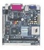
Chapter 1 Specifications The ultra-compact and highly intergrated VIA EPIA-M Mini-ITX Mainboard is the smallest form factor mainboard specification available today, developed by VIA Technologies, Inc. This chapter includes the following sections: Mainboard Specifications 1-2 Mainboard Layout 1-4 Back Panel Ports 1-5 Slots 1-5 Connectors / Jumpers 1-6 1-1 The mainboard comes with an embedded VIA Processor, boasting ultra low power consumption and...
Chapter 1 Specifications The ultra-compact and highly intergrated VIA EPIA-M Mini-ITX Mainboard is the smallest form factor mainboard specification available today, developed by VIA Technologies, Inc. This chapter includes the following sections: Mainboard Specifications 1-2 Mainboard Layout 1-4 Back Panel Ports 1-5 Slots 1-5 Connectors / Jumpers 1-6 1-1 The mainboard comes with an embedded VIA Processor, boasting ultra low power consumption and...

User Manual
Page 10
...-in; can be switched to 6 channel output with Smart 5.1 (See Appendix A) BIOS • AwardBIOS with 2 / 4Mbit flash memory Form Factor • 17 cm X 17 cm Mini-ITX (4 layers) 1-3
...-in; can be switched to 6 channel output with Smart 5.1 (See Appendix A) BIOS • AwardBIOS with 2 / 4Mbit flash memory Form Factor • 17 cm X 17 cm Mini-ITX (4 layers) 1-3

User Manual
Page 15
... fan does not have a sensor. Ensure that the red wire is Ground and should be connected to the +12V. Chapter 2 CPU The VIA EPIA-M Mini-ITX Mainboard includes an embedded VIA Eden Processor or VIA C3TM E-Series Processor. The CPUFAN (CPU fan) and SYSFAN (system fan) run on +12V and maintain system cooling. The black wire...
... fan does not have a sensor. Ensure that the red wire is Ground and should be connected to the +12V. Chapter 2 CPU The VIA EPIA-M Mini-ITX Mainboard includes an embedded VIA Eden Processor or VIA C3TM E-Series Processor. The CPUFAN (CPU fan) and SYSFAN (system fan) run on +12V and maintain system cooling. The black wire...

User Manual
Page 17
DDR SDRAM Module Installation Procedures 1. With both hands, press the DDR SDRAM module down into the DIMM slot so that the white retaining latches rotate up and secure the module in the correct position. 3. Push the white retaining latches at either end of the DIMM slot outwards. 2. Align the DDR SDRAM module with the corresponding notches on the DIMM slot. The modules will only fit if placed in place (see picture below). 2-4 Chapter 2 Memory Module Installation The VIA EPIA-M Mini-ITX Mainboard provides one 184-pin DIMM slot for DDR266 SDRAM memory modules.
DDR SDRAM Module Installation Procedures 1. With both hands, press the DDR SDRAM module down into the DIMM slot so that the white retaining latches rotate up and secure the module in the correct position. 3. Push the white retaining latches at either end of the DIMM slot outwards. 2. Align the DDR SDRAM module with the corresponding notches on the DIMM slot. The modules will only fit if placed in place (see picture below). 2-4 Chapter 2 Memory Module Installation The VIA EPIA-M Mini-ITX Mainboard provides one 184-pin DIMM slot for DDR266 SDRAM memory modules.

User Manual
Page 19
... 3.3V 12 -12V 13 GND 14 PS_ON 15 GND 16 GND 17 GND 18 NC 19 5V 20 5V 2-6 Chapter 2 Connecting the Power Supply The VIA EPIA-M Mini-ITX Mainboard requires an ATX power supply to ensure that all components are correctly aligned. Before inserting the power supply connector, always make sure the plugs...
... 3.3V 12 -12V 13 GND 14 PS_ON 15 GND 16 GND 17 GND 18 NC 19 5V 20 5V 2-6 Chapter 2 Connecting the Power Supply The VIA EPIA-M Mini-ITX Mainboard requires an ATX power supply to ensure that all components are correctly aligned. Before inserting the power supply connector, always make sure the plugs...