User Manual
Page 6
... 1 Mainboard Specifications 2 Mainboard Layout 4 Back Panel Layout 5 Back Panel Ports 6 Slots 6 Onboard Connectors 7 Onboard Jumpers 7 Chapter 2 9 Installation 9 CPU 10 Memory Module Installation 12 Connecting the Power Supply 13 Back Panel Ports 14 Connectors 16 Jumpers 23 Slots 25 Chapter 3 27 BIOS Setup 27 Entering Setup 28 Control Keys 29 Navigating the BIOS...
... 1 Mainboard Specifications 2 Mainboard Layout 4 Back Panel Layout 5 Back Panel Ports 6 Slots 6 Onboard Connectors 7 Onboard Jumpers 7 Chapter 2 9 Installation 9 CPU 10 Memory Module Installation 12 Connecting the Power Supply 13 Back Panel Ports 14 Connectors 16 Jumpers 23 Slots 25 Chapter 3 27 BIOS Setup 27 Entering Setup 28 Control Keys 29 Navigating the BIOS...

User Manual
Page 21
... correctly to ensure that all components are aligned. Then push down the plug firmly into the connector. ATX 20-Pin Power Connector To connect the ATX power supply, make sure that no damage will be caused. Pin Signal 1 +3.3V 2 +3.3V 3 GND 4 +5V 5 GND 6 +...5V 7 GND 8 Power Good 9 +5V Standby 10 +12V 11 +3.3V 12 -12V 13 GND 14 Power Supply On 15 GND 16 GND 17 GND 18 -5V 19 +5V 20 +5V ATXPWR 11 1 20 10 13 Installation CONNECTING THE POWER SUPPLY The VIA EPIA-EX Mini-ITX mainboard supports a conventional ATX...
... correctly to ensure that all components are aligned. Then push down the plug firmly into the connector. ATX 20-Pin Power Connector To connect the ATX power supply, make sure that no damage will be caused. Pin Signal 1 +3.3V 2 +3.3V 3 GND 4 +5V 5 GND 6 +...5V 7 GND 8 Power Good 9 +5V Standby 10 +12V 11 +3.3V 12 -12V 13 GND 14 Power Supply On 15 GND 16 GND 17 GND 18 -5V 19 +5V 20 +5V ATXPWR 11 1 20 10 13 Installation CONNECTING THE POWER SUPPLY The VIA EPIA-EX Mini-ITX mainboard supports a conventional ATX...

User Manual
Page 28
... 1 IVDD 2 IVDD 3 BLON 4 NC 5 BLON 6 BR_CNTR 7 GND 8 GND Serial ATA Connectors: SATA1 and SATA2 These next generation connectors support the thin Serial ATA cables for supplying power to the backlight of the LCD panel. The current Serial ATA interface allows up to connect SMBUS (System Management Bus) devices. Devices communicate with 133...
... 1 IVDD 2 IVDD 3 BLON 4 NC 5 BLON 6 BR_CNTR 7 GND 8 GND Serial ATA Connectors: SATA1 and SATA2 These next generation connectors support the thin Serial ATA cables for supplying power to the backlight of the LCD panel. The current Serial ATA interface allows up to connect SMBUS (System Management Bus) devices. Devices communicate with 133...
User Manual
Page 31
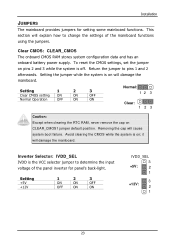
.... Avoid clearing the CMOS while the system is off. Clear CMOS: CLEAR_CMOS The onboard CMOS RAM stores system configuration data and has an onboard battery power supply. Installation JUMPERS The mainboard provides jumpers for panel's back-light. it will cause system boot failure. This section will damage the mainboard.
.... Avoid clearing the CMOS while the system is off. Clear CMOS: CLEAR_CMOS The onboard CMOS RAM stores system configuration data and has an onboard battery power supply. Installation JUMPERS The mainboard provides jumpers for panel's back-light. it will cause system boot failure. This section will damage the mainboard.

User Manual
Page 33
... line) are hardware lines over which devices can send interrupt signals to insert PCI expansion card. When adding or removing expansion card, unplug first the power supply.
... line) are hardware lines over which devices can send interrupt signals to insert PCI expansion card. When adding or removing expansion card, unplug first the power supply.

User Manual
Page 61
...Safe Defaults ESC: Exit F1: General Help F7: Optimized Defaults ACPI Suspend Type Setting S1(POS) S3(STR) S1 & S3 Description S1/Power On Suspend (POS) is a power-down the hard disk. In this state, no system context (CPU or chipset) is saved to essential components such as main memory and..., 1 Min, 2 Min, 4 Min, 6 Min, 8 Min, 10 Min, 20 Min, 30 Min, 40 Min, 1 Hour] 53 Depends on the OS to select S1 or S3. POWER MANAGEMENT SETUP BIOS Setup Phoenix - In this state, power is supplied only to main memory, and context is restored from the memory when a "wakeup" event occurs.
...Safe Defaults ESC: Exit F1: General Help F7: Optimized Defaults ACPI Suspend Type Setting S1(POS) S3(STR) S1 & S3 Description S1/Power On Suspend (POS) is a power-down the hard disk. In this state, no system context (CPU or chipset) is saved to essential components such as main memory and..., 1 Min, 2 Min, 4 Min, 6 Min, 8 Min, 10 Min, 20 Min, 30 Min, 40 Min, 1 Hour] 53 Depends on the OS to select S1 or S3. POWER MANAGEMENT SETUP BIOS Setup Phoenix - In this state, power is supplied only to main memory, and context is restored from the memory when a "wakeup" event occurs.