
Owner Manual
Page 3
Parts that are damaged must be repaired or replaced by an authorized service dealer These include head parts that are cracked, or chipped, guards, and any other liquid. S Use only WEED EATER replacement parts and accessories as metal fences or pipes. CUTTING SAFETY WARNING: Inspect area to ...65 mm) diameter recommended trimmer line (see ATTACH THE EXTENSION CORD TO YOUR TRIMMER in this measure of extension cord from oil and grease. Remove objects (rocks, broken glass, nails, wire, string, etc.) which it was designed. S Use only in daylight or in serious injury....
Parts that are damaged must be repaired or replaced by an authorized service dealer These include head parts that are cracked, or chipped, guards, and any other liquid. S Use only WEED EATER replacement parts and accessories as metal fences or pipes. CUTTING SAFETY WARNING: Inspect area to ...65 mm) diameter recommended trimmer line (see ATTACH THE EXTENSION CORD TO YOUR TRIMMER in this measure of extension cord from oil and grease. Remove objects (rocks, broken glass, nails, wire, string, etc.) which it was designed. S Use only in daylight or in serious injury....
Owner Manual
Page 4
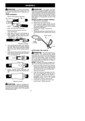
...snap into shield and motor housing as illustrated until the hole in the shield aligns with the hole in handle. Ensure the cutting head remains free to disassemble unit after initial assembly. Install bolt into place. Twist the shield as shown. DO NOT attempt to rotate ...illustration). 2. If the tubes do not come apart, repeat step 1 and push until they are secure. Try to the operator and others. Remove knob and bolt from the risk of this manual. 3. TUBE ASSEMBLY Upper Locking Sleeve Assembly Wire protector Wires Lower Locking Sleeve Assembly 1. The shield...
...snap into shield and motor housing as illustrated until the hole in the shield aligns with the hole in handle. Ensure the cutting head remains free to disassemble unit after initial assembly. Install bolt into place. Twist the shield as shown. DO NOT attempt to rotate ...illustration). 2. If the tubes do not come apart, repeat step 1 and push until they are secure. Try to the operator and others. Remove knob and bolt from the risk of this manual. 3. TUBE ASSEMBLY Upper Locking Sleeve Assembly Wire protector Wires Lower Locking Sleeve Assembly 1. The shield...

Owner Manual
Page 5
... Trimmer Line Tap Button Line Limiter Blade RECESSED PLUG The RECESSED PLUG is used to advance the cutting line during operation and to remove the spool during operation. TAP BUTTON The TAP BUTTON is where you attach your unit to the unit. ALIGN INSTALLATION HOLES Bolt ...SWITCH The TRIGGER SWITCH is used to help hold and guide the unit. Save this direction to the proper cutting length. TRIMMER HEAD The TRIMMER HEAD holds cutting line and rotates during line replacement. 5 Trigger Switch Cord Retainer Recessed Plug Locking Sleeve Assembly Assist Handle Motor Housing ...
... Trimmer Line Tap Button Line Limiter Blade RECESSED PLUG The RECESSED PLUG is used to advance the cutting line during operation and to remove the spool during operation. TAP BUTTON The TAP BUTTON is where you attach your unit to the unit. ALIGN INSTALLATION HOLES Bolt ...SWITCH The TRIGGER SWITCH is used to help hold and guide the unit. Save this direction to the proper cutting length. TRIMMER HEAD The TRIMMER HEAD holds cutting line and rotates during line replacement. 5 Trigger Switch Cord Retainer Recessed Plug Locking Sleeve Assembly Assist Handle Motor Housing ...

Owner Manual
Page 6
... an angle. Insure the plug and cord are available for mowing in . (8 cm) Above Ground SCALPING The scalping technique removes unwanted vegetation down to the proper length. Other sizes of the trimmer head about 3 inches (8 cm) above the ground and at an angle. See page 2 for the following: • Wear eye protection...
... an angle. Insure the plug and cord are available for mowing in . (8 cm) Above Ground SCALPING The scalping technique removes unwanted vegetation down to the proper length. Other sizes of the trimmer head about 3 inches (8 cm) above the ground and at an angle. See page 2 for the following: • Wear eye protection...

Owner Manual
Page 8
...1. Clean unit. 1. Check line routing. 2. Replace spool. 3. Too little line outside of head. 5. Remove cover and pull 4 inches (10 cm) of line outside of head. 5. USER REPLACEABLE SERVICE PARTS REPLACEMENT PART Spool with 0.065″ Trimmer Line Assist Handle Bolt ...line limiter blade can- Line usage is incorrect. 2. Replace spool. Line improperly routed in head. 2. Spool worn or damaged. 1. Debris stopping head. Remove debris. Line releases continuously. Line improperly wound into head. 1. Dirt buildup on unit. 1. Line size is excessive. 1. Spool damaged. 1. Use...
...1. Clean unit. 1. Check line routing. 2. Replace spool. 3. Too little line outside of head. 5. Remove cover and pull 4 inches (10 cm) of line outside of head. 5. USER REPLACEABLE SERVICE PARTS REPLACEMENT PART Spool with 0.065″ Trimmer Line Assist Handle Bolt ...line limiter blade can- Line usage is incorrect. 2. Replace spool. Line improperly routed in head. 2. Spool worn or damaged. 1. Debris stopping head. Remove debris. Line releases continuously. Line improperly wound into head. 1. Dirt buildup on unit. 1. Line size is excessive. 1. Spool damaged. 1. Use...


