

Owner Manual
Page 3
...to have the unit repaired by the manufacturer. sulated appliance must be added to this unit, including housing, switch, motor, locking sleeve assembly, wires, etc., must be made by the extension cord or yank extension cord to plug movement (see USER REPLACEABLE SERVICE PARTS in serious...Do not expose cords to recommended procedures. Make sure all parts are in cutting head. S Do not repair unit yourself. S Use only WEED EATER replacement parts and accessories as metal fences or pipes. S Have all times. TRANSPORTING AND STORAGE S Stop the unit and disconnect the power ...
...to have the unit repaired by the manufacturer. sulated appliance must be added to this unit, including housing, switch, motor, locking sleeve assembly, wires, etc., must be made by the extension cord or yank extension cord to plug movement (see USER REPLACEABLE SERVICE PARTS in serious...Do not expose cords to recommended procedures. Make sure all parts are in cutting head. S Do not repair unit yourself. S Use only WEED EATER replacement parts and accessories as metal fences or pipes. S Have all times. TRANSPORTING AND STORAGE S Stop the unit and disconnect the power ...
Owner Manual
Page 4
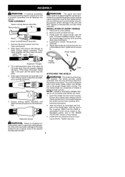
...damage to completely en- Adjust the handle up or down (see illustration). 4. Try to the unit as shown. Ensure locking sleeve assembly and alignment decals appear as illustrated until the tubes snap into place. Alignment decals Trigger housing Tube ATTACHING THE SHIELD WARNING: The ...are properly snapped into shield and motor housing as shown in the illustration below . Firmly push the assist handle over lower locking sleeve assembly and tighten by turning clockwise. 5. To make installation easier, tilt handle toward trigger housing while pushing down the tube to unit (...
...damage to completely en- Adjust the handle up or down (see illustration). 4. Try to the unit as shown. Ensure locking sleeve assembly and alignment decals appear as illustrated until the tubes snap into place. Alignment decals Trigger housing Tube ATTACHING THE SHIELD WARNING: The ...are properly snapped into shield and motor housing as shown in the illustration below . Firmly push the assist handle over lower locking sleeve assembly and tighten by turning clockwise. 5. To make installation easier, tilt handle toward trigger housing while pushing down the tube to unit (...

Owner Manual
Page 5
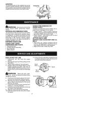
.... Release to turn on the unit. TAP BUTTON The TAP BUTTON is used to advance the cutting line during operation and to assemble CAUTION: Sharp line limiter blade OPERATION KNOW YOUR TRIMMER READ THIS INSTRUCTION MANUAL AND SAFETY RULES BEFORE OPERATING YOUR UNIT. ALIGN INSTALLATION ...attach your unit to familiarize yourself with 0.065 in this manual for future reference. Trigger Switch Cord Retainer Recessed Plug Locking Sleeve Assembly Assist Handle Motor Housing Air Vents Debris Shield Trimmer Head with the location of the various controls and adjustments. Trimmer Line Tap Button...
.... Release to turn on the unit. TAP BUTTON The TAP BUTTON is used to advance the cutting line during operation and to assemble CAUTION: Sharp line limiter blade OPERATION KNOW YOUR TRIMMER READ THIS INSTRUCTION MANUAL AND SAFETY RULES BEFORE OPERATING YOUR UNIT. ALIGN INSTALLATION ...attach your unit to familiarize yourself with 0.065 in this manual for future reference. Trigger Switch Cord Retainer Recessed Plug Locking Sleeve Assembly Assist Handle Motor Housing Air Vents Debris Shield Trimmer Head with the location of the various controls and adjustments. Trimmer Line Tap Button...
Owner Manual
Page 7
...by pressing and releasing the trigger switch. Insert one end of the line about 1/2 inch (1 cm) into place. 11. Push the spool into the hub until it from the notch; Clean entire surface of heavier lines could overload and ...from the power source. 2. BEFORE EACH USE CHECK FOR LOOSE FASTENERS AND PARTS • Housing Screws • Locking Sleeve Assembly • Assist Handle • Debris Shield CHECK FOR DAMAGED OR WORN PARTS Contact an authorized service dealer for loose or ...the hub to side. WARNING: Never use of 0.065″ (1.65 mm) diameter WEED EATER brand line.
...by pressing and releasing the trigger switch. Insert one end of the line about 1/2 inch (1 cm) into place. 11. Push the spool into the hub until it from the notch; Clean entire surface of heavier lines could overload and ...from the power source. 2. BEFORE EACH USE CHECK FOR LOOSE FASTENERS AND PARTS • Housing Screws • Locking Sleeve Assembly • Assist Handle • Debris Shield CHECK FOR DAMAGED OR WORN PARTS Contact an authorized service dealer for loose or ...the hub to side. WARNING: Never use of 0.065″ (1.65 mm) diameter WEED EATER brand line.

Owner Manual
Page 8
... before performing all guards in place. USER REPLACEABLE SERVICE PARTS REPLACEMENT PART Spool with 0.065″ Trimmer Line Assist Handle Bolt Carriage, M6x1 Knob Shield Assembly Bolt PART NUMBER 952701663 574473001 574473201 574473101 574471501 574471601 STORAGE WARNING: Perform the following steps after each use. • Stop the unit and disconnect the...
... before performing all guards in place. USER REPLACEABLE SERVICE PARTS REPLACEMENT PART Spool with 0.065″ Trimmer Line Assist Handle Bolt Carriage, M6x1 Knob Shield Assembly Bolt PART NUMBER 952701663 574473001 574473201 574473101 574471501 574471601 STORAGE WARNING: Perform the following steps after each use. • Stop the unit and disconnect the...
Parts List
Page 1
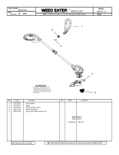
...3. 574473201 4. 574471501 5. 952701663 Description Assit Handle Knob Bolt Carriage, M6 X 1 Shield Assembly Spool with 0.065" Trimmer line Ref. Parts List No. 966047801 Date 02/24/10 NEW WEED EATER R PARTS LIST NOTE : Illustration may differ from actual model due to the Service Reference ...Indicated for more information.(Located at the END of the IPL) Part No. 5 Description Not Shown 115253326 Manual = New Part Number For This IPL = Refer to design changes. 1 2 MODEL WE EL-11...
...3. 574473201 4. 574471501 5. 952701663 Description Assit Handle Knob Bolt Carriage, M6 X 1 Shield Assembly Spool with 0.065" Trimmer line Ref. Parts List No. 966047801 Date 02/24/10 NEW WEED EATER R PARTS LIST NOTE : Illustration may differ from actual model due to the Service Reference ...Indicated for more information.(Located at the END of the IPL) Part No. 5 Description Not Shown 115253326 Manual = New Part Number For This IPL = Refer to design changes. 1 2 MODEL WE EL-11...


