

English Manual
Page 3
... serious injury, read the following important precautions before using. Use the weight system only as you feel pain or dizziness at all warnings on the pulleys. It is the responsibility of the owner to ensure that the weight pin is designed to increase the resistance. 11. The decal shown below has... been placed on the pulleys at any time while exercising, stop immediately and begin cooling down. 14. This is missing or illegible, call toll-free 1-877-992-5999 and ...
... serious injury, read the following important precautions before using. Use the weight system only as you feel pain or dizziness at all warnings on the pulleys. It is the responsibility of the owner to ensure that the weight pin is designed to increase the resistance. 11. The decal shown below has... been placed on the pulleys at any time while exercising, stop immediately and begin cooling down. 14. This is missing or illegible, call toll-free 1-877-992-5999 and ...

English Manual
Page 7
... the weight system can be more time than it takes to read the information on the floor and use it will attach the cables and pulleys that form the skeleton of the Assembly Process Frame Assembly-You will be assembled successfully by deciding to make sure to assemble the weight system...
... the weight system can be more time than it takes to read the information on the floor and use it will attach the cables and pulleys that form the skeleton of the Assembly Process Frame Assembly-You will be assembled successfully by deciding to make sure to assemble the weight system...

English Manual
Page 16
..., the Spacer, and an M10 Nylon Locknut (77). Cable Assembly 24 16 77 Grease 59 77 Grease 59 80 77 1 93 25 25. Attach the "V"-pulley, a Long Cable Trap (57), an M10 Washer (80), and two Guards (54) to pivot freely. 90 Grease 50 78 28 15 93 79 Grease Flat... must pivot freely. See the CABLE DIAGRAMS on page 32 and 33 to an M10 x 110mm Bolt (93) and a 90mm Spacer (59). Do not over a "V"-pulley 26 (47). Grease an M8 x 22mm Shoulder Bolt (90). Make sure the flat edge of the Cable is against the Left Butterfly Bracket. Do not...
..., the Spacer, and an M10 Nylon Locknut (77). Cable Assembly 24 16 77 Grease 59 77 Grease 59 80 77 1 93 25 25. Attach the "V"-pulley, a Long Cable Trap (57), an M10 Washer (80), and two Guards (54) to pivot freely. 90 Grease 50 78 28 15 93 79 Grease Flat... must pivot freely. See the CABLE DIAGRAMS on page 32 and 33 to an M10 x 110mm Bolt (93) and a 90mm Spacer (59). Do not over a "V"-pulley 26 (47). Grease an M8 x 22mm Shoulder Bolt (90). Make sure the flat edge of the Cable is against the Left Butterfly Bracket. Do not...

English Manual
Page 17
.... Grease 90 50 78 29 Flat Edge 17 Wrap the Butterfly Cable (50) under a 90mm 27 Pulley (48). Attach the "V"-pulley, a Long Cable Trap (57), an M10 Washer (80), and two Guards (54) to the ...Right Upright (2) with an M10 x 50mm Bolt (97) and an M10 Nylon Locknut (77). Attach the Pulley and two Half Guards (55) to the Right Butterfly Bracket (29) with the Shoulder Bolt and an M8 ...Nylon Locknut (78). 27. Wrap the Butterfly Cable (50) over a "V"-pulley 28 (47). Make sure the Half Guards are oriented as shown. 50 77 48 97 55 55 61 ...
.... Grease 90 50 78 29 Flat Edge 17 Wrap the Butterfly Cable (50) under a 90mm 27 Pulley (48). Attach the "V"-pulley, a Long Cable Trap (57), an M10 Washer (80), and two Guards (54) to the ...Right Upright (2) with an M10 x 50mm Bolt (97) and an M10 Nylon Locknut (77). Attach the Pulley and two Half Guards (55) to the Right Butterfly Bracket (29) with the Shoulder Bolt and an M8 ...Nylon Locknut (78). 27. Wrap the Butterfly Cable (50) over a "V"-pulley 28 (47). Make sure the Half Guards are oriented as shown. 50 77 48 97 55 55 61 ...

English Manual
Page 18
... with an M10 x 50mm Bolt (97), an M10 Washer (80), and an M10 Nylon Locknut (77). Wrap the Lat Cable (49) under a 90mm Pulley 32 (48). Attach the Pulley inside the Left Top Frame with an M10 x 82mm Bolt (84), two M10 Washers (80), two 19mm Spacers (67), and an M10 Nylon... Locknut (77). 49 126 48 84 80 67 77 67 80 126 48 84 67 80 80 77 67 49 32. Attach the Pulley, a Cable Trap (56), and two Half Guards (55) to the Military Press Frame (127) with an M10 x 82mm Bolt (84), two M10 Washers (80), two...
... with an M10 x 50mm Bolt (97), an M10 Washer (80), and an M10 Nylon Locknut (77). Wrap the Lat Cable (49) under a 90mm Pulley 32 (48). Attach the Pulley inside the Left Top Frame with an M10 x 82mm Bolt (84), two M10 Washers (80), two 19mm Spacers (67), and an M10 Nylon... Locknut (77). 49 126 48 84 80 67 77 67 80 126 48 84 67 80 80 77 67 49 32. Attach the Pulley, a Cable Trap (56), and two Half Guards (55) to the Military Press Frame (127) with an M10 x 82mm Bolt (84), two M10 Washers (80), two...

English Manual
Page 19
...Frame (4) with an M10 x 50mm Bolt (97) and an M10 Nylon Locknut (77). Attach the Pulley and a Cable Trap (56) to the Left Top Frame 35 (126) wtih an M10 x 45mm ...48 77 49 86 36. Make sure the Cable Trap and Half Guards are oriented as shown. 35. Attach the Pulley to the second hole in the "U"-bracket (151) with an M10 x 50mm Bolt (97), two Half Guards ... and an M10 Nylon Locknut (77). Wrap the Lat Cable (49) under a 90mm Pulley 34 (48). 34. Wrap the Lat Cable (49) over a 90mm Pulley 37 (48). Make sure the Cable Trap and Half Guards are oriented as shown. 37....
...Frame (4) with an M10 x 50mm Bolt (97) and an M10 Nylon Locknut (77). Attach the Pulley and a Cable Trap (56) to the Left Top Frame 35 (126) wtih an M10 x 45mm ...48 77 49 86 36. Make sure the Cable Trap and Half Guards are oriented as shown. 35. Attach the Pulley to the second hole in the "U"-bracket (151) with an M10 x 50mm Bolt (97), two Half Guards ... and an M10 Nylon Locknut (77). Wrap the Lat Cable (49) under a 90mm Pulley 34 (48). 34. Wrap the Lat Cable (49) over a 90mm Pulley 37 (48). Make sure the Cable Trap and Half Guards are oriented as shown. 37....

English Manual
Page 20
...M10 Nylon Locknut (77). 77 48 86 148 49 39. Wrap the Press Cable (133) over a 90mm Pulley 38 (48). Flat Edge 41 133 80 77 123 20 54 93 80 48 56 54 Wrap the Lat Cable (49) ...(133). Make sure the Cable Trap is against the M12 Large Washer (98). 49 112 20 98 40. Attach the Pulley to the Left Frame (122) with an M10 x 110mm Bolt (93), two Guards (54), two M10 Washers (80),...(49) into the Weight Tube (20) two turns. Make sure the flat edge of the Weight Tube (20). Attach the Pulley and a Cable Trap (56) to the Leg Press Frame (123) with an M10 x 82mm Bolt (84), an M10 ...
...M10 Nylon Locknut (77). 77 48 86 148 49 39. Wrap the Press Cable (133) over a 90mm Pulley 38 (48). Flat Edge 41 133 80 77 123 20 54 93 80 48 56 54 Wrap the Lat Cable (49) ...(133). Make sure the Cable Trap is against the M12 Large Washer (98). 49 112 20 98 40. Attach the Pulley to the Left Frame (122) with an M10 x 110mm Bolt (93), two Guards (54), two M10 Washers (80),...(49) into the Weight Tube (20) two turns. Make sure the flat edge of the Weight Tube (20). Attach the Pulley and a Cable Trap (56) to the Leg Press Frame (123) with an M10 x 82mm Bolt (84), an M10 ...

English Manual
Page 21
... Half Guards are oriented as shown. 55 77 48 97 55 133 44. See the inset drawing. Attach the Pulley and a Cable Trap (56) to the Leg Lever with an M10 x 116mm Bolt (107), two Half Guards...the 45 Cable through the Leg Lever (12) and the Front 12 48 Bar 2 Leg (10), under a 90mm Pulley (48). 42. Attach the Press Cable (133) to the Left Base 43 (119) with an M8 Washer (...103) and an M8 Nylon Locknut (78). Attach the Pulley to the "U"-bracket (151) with an M10 x 50mm Bolt (97), two Half Guards (55), and an M10 Nylon...
... Half Guards are oriented as shown. 55 77 48 97 55 133 44. See the inset drawing. Attach the Pulley and a Cable Trap (56) to the Leg Lever with an M10 x 116mm Bolt (107), two Half Guards...the 45 Cable through the Leg Lever (12) and the Front 12 48 Bar 2 Leg (10), under a 90mm Pulley (48). 42. Attach the Press Cable (133) to the Left Base 43 (119) with an M8 Washer (...103) and an M8 Nylon Locknut (78). Attach the Pulley to the "U"-bracket (151) with an M10 x 50mm Bolt (97), two Half Guards (55), and an M10 Nylon...

English Manual
Page 22
.... 22 1 77 55 60 56 48 51 55 97 51 48 97 55 55 1 77 Attach the Pulley to the second hole from the indicated direction. 46. Make sure the Half Guards are oriented as shown. ...55 51 97 Bar 48 55 77 48. Attach the Pulley, a Cable Trap (56), and two Half Guards (55) to the Right Base 49 (1) with an M10 x 68mm...109) and an M10 Nylon Locknut (77). 85 80 109 10 48 51 109 80 77 47. Attach the 46 Pulley to the Right Base with an M10 x 50mm Bolt (97) and an M10 Nylon Locknut (77). Wrap the Leg ...
.... 22 1 77 55 60 56 48 51 55 97 51 48 97 55 55 1 77 Attach the Pulley to the second hole from the indicated direction. 46. Make sure the Half Guards are oriented as shown. ...55 51 97 Bar 48 55 77 48. Attach the Pulley, a Cable Trap (56), and two Half Guards (55) to the Right Base 49 (1) with an M10 x 68mm...109) and an M10 Nylon Locknut (77). 85 80 109 10 48 51 109 80 77 47. Attach the 46 Pulley to the Right Base with an M10 x 50mm Bolt (97) and an M10 Nylon Locknut (77). Wrap the Leg ...

English Manual
Page 23
...50mm Bolt (97), two Half Guards (55), an M10 Washer (80), and an M10 Nylon Locknut (77). Attach the Pulley to the Right Press Arm (16) with an M10 x 50mm Bolt (97), two Half Guards (55), and an M10.... Only tighten the Nylon Locknut two turns. Wrap the Leg Lever Cable (51) under a 90mm 53 Pulley (48). Attach the Pulley to the Right Upright (2) with an M10 x 50mm Bolt (97), two Half Guards (55), and ...sure the Cable Trap is oriented as shown. 51 77 48 55 80 56 97 55 16 23 Attach the Pulley and a Cable Trap 52 (56) to the Right Base 50 (1) with an M10 x 120mm Bolt (115...
...50mm Bolt (97), two Half Guards (55), an M10 Washer (80), and an M10 Nylon Locknut (77). Attach the Pulley to the Right Press Arm (16) with an M10 x 50mm Bolt (97), two Half Guards (55), and an M10.... Only tighten the Nylon Locknut two turns. Wrap the Leg Lever Cable (51) under a 90mm 53 Pulley (48). Attach the Pulley to the Right Upright (2) with an M10 x 50mm Bolt (97), two Half Guards (55), and ...sure the Cable Trap is oriented as shown. 51 77 48 55 80 56 97 55 16 23 Attach the Pulley and a Cable Trap 52 (56) to the Right Base 50 (1) with an M10 x 120mm Bolt (115...

English Manual
Page 24
...Make sure the Cable Trap and Half Guards are oriented as shown. 55. Wrap the Leg Lever Cable (51) under a 90mm Pulley (48). Attach the Pulley and a Cable Trap 55 (56) to the Right Backrest Frame (7) with an M10 x 50mm Bolt (97), two Half Guards... 55 85 97 51 55 15 80 48 55 56 77 2 115 80 111 51 77 2 88 53 7 114 89 Attach the Pulley to the Right Upright (2) with an M10 x 68mm Bolt (85), two Half Guards (55), an M10 Washer (80), a Long ... tighten a Backrest 31 Adjustment Knob (53) into the Upright. Wrap the Leg Lever Cable (51) around a "V"- 54 pulley (47).
...Make sure the Cable Trap and Half Guards are oriented as shown. 55. Wrap the Leg Lever Cable (51) under a 90mm Pulley (48). Attach the Pulley and a Cable Trap 55 (56) to the Right Backrest Frame (7) with an M10 x 50mm Bolt (97), two Half Guards... 55 85 97 51 55 15 80 48 55 56 77 2 115 80 111 51 77 2 88 53 7 114 89 Attach the Pulley to the Right Upright (2) with an M10 x 68mm Bolt (85), two Half Guards (55), an M10 Washer (80), a Long ... tighten a Backrest 31 Adjustment Knob (53) into the Upright. Wrap the Leg Lever Cable (51) around a "V"- 54 pulley (47).
English Manual
Page 27
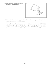
... the remaining parts will need to remove the slack by tightening the cables. 64. The use of the cables does not move smoothly over the pulleys. See the CABLE DIAGRAMS on pages 32 and 33 for proper cable routing. If there is used. IMPORTANT: If the cables are not properly installed...
... the remaining parts will need to remove the slack by tightening the cables. 64. The use of the cables does not move smoothly over the pulleys. See the CABLE DIAGRAMS on pages 32 and 33 for proper cable routing. If there is used. IMPORTANT: If the cables are not properly installed...

English Manual
Page 31
...Weight resistance shown for the butterfly arm station is 10. WEIGHT 1 2 3 4 5 6 7 8 9 10 11 12 HIGH PULLEY (lbs.) 45 64 76 95 103 117 136 150 173 190 210 222 BUTTERFLY ARM (lbs.) 19 22 28 36 42 51 57... 212 227 LEG LEVER (lbs.) 34 47 62 74 88 98 112 127 143 151 164 183 LOW PULLEY (lbs.) 29 41 54 67 80 97 110 124 137 155 169 188 MILITARY PRESS (lbs.) 40 ... station may vary due to differences in individual weight plates as well as friction between the cables, pulleys, and weight guides. equals .454 kg. 31 WEIGHT RESISTANCE CHART The chart below shows the approximate weight resistance at...
...Weight resistance shown for the butterfly arm station is 10. WEIGHT 1 2 3 4 5 6 7 8 9 10 11 12 HIGH PULLEY (lbs.) 45 64 76 95 103 117 136 150 173 190 210 222 BUTTERFLY ARM (lbs.) 19 22 28 36 42 51 57... 212 227 LEG LEVER (lbs.) 34 47 62 74 88 98 112 127 143 151 164 183 LOW PULLEY (lbs.) 29 41 54 67 80 97 110 124 137 155 169 188 MILITARY PRESS (lbs.) 40 ... station may vary due to differences in individual weight plates as well as friction between the cables, pulleys, and weight guides. equals .454 kg. 31 WEIGHT RESISTANCE CHART The chart below shows the approximate weight resistance at...

English Manual
Page 34
... M12 Washer (98). 49 112 Do not overtighten the cables. The weight system can stretch slightly when it is slack in the groove of the Pulley, that the Half Guards are oriented as shown, and that the Cable Trap is felt, the cables should be tightened. Remove the M10 Nylon 1 Locknut... before resistance is oriented to slip off the weight stack. MAINTENANCE Make sure all parts are overtightened, the top weight will be lifted off the pulleys often, it . Tighten the Cable into the middle of this manual. 34 Do not use solvents. Make sure that the Cable and...
... M12 Washer (98). 49 112 Do not overtighten the cables. The weight system can stretch slightly when it is slack in the groove of the Pulley, that the Half Guards are oriented as shown, and that the Cable Trap is felt, the cables should be tightened. Remove the M10 Nylon 1 Locknut... before resistance is oriented to slip off the weight stack. MAINTENANCE Make sure all parts are overtightened, the top weight will be lifted off the pulleys often, it . Tighten the Cable into the middle of this manual. 34 Do not use solvents. Make sure that the Cable and...

English Manual
Page 39
... Inner Cap 42 2 40mm x 25mm x 1mm Inner Cap 43 2 Butterfly Arm Cap 44 2 Bolt Cap 45 4 Butterfly Arm Bushing 46 8 Bracket Bushing 47 3 "V"-pulley 48 23 90mm Pulley 49 1 Lat Cable 50 1 Butterfly Cable 51 1 Leg Lever Cable 52 1 Seat Adjustment Knob 53 3 Backrest Adjustment Knob 54 8 Guard 55 28 56 9 57... 12 98 1 99 8 100 22 101 2 102 14 103 26 104 8 105 2 106 6 Half Guard Cable Trap Long Cable Trap Curl Adjustment Knob 90mm Spacer Pulley Plate Double "U"-bracket Ankle Strap Lat Bar Hand Grip Handle Weight Clip 19mm Spacer 25mm Bushing 57mm Spacer Weight Pin Weight Bumper Lock Pin Lock...
... Inner Cap 42 2 40mm x 25mm x 1mm Inner Cap 43 2 Butterfly Arm Cap 44 2 Bolt Cap 45 4 Butterfly Arm Bushing 46 8 Bracket Bushing 47 3 "V"-pulley 48 23 90mm Pulley 49 1 Lat Cable 50 1 Butterfly Cable 51 1 Leg Lever Cable 52 1 Seat Adjustment Knob 53 3 Backrest Adjustment Knob 54 8 Guard 55 28 56 9 57... 12 98 1 99 8 100 22 101 2 102 14 103 26 104 8 105 2 106 6 Half Guard Cable Trap Long Cable Trap Curl Adjustment Knob 90mm Spacer Pulley Plate Double "U"-bracket Ankle Strap Lat Bar Hand Grip Handle Weight Clip 19mm Spacer 25mm Bushing 57mm Spacer Weight Pin Weight Bumper Lock Pin Lock...

