

English Manual
Page 1
Save this equipment. Model No. 831.14623.0 Serial No. WEIGHT SYSTEM EXERCISER User's Manual Serial Number Decal (under seat) • Assembly • Adjustments • Troubleshooting • Part List and Drawing CAUTION Read all precautions and instructions in the space above for future reference. Sears, Roebuck and Co., Hoffman Estates, IL 60179 Write the serial number in this manual before using this manual for future reference.
Save this equipment. Model No. 831.14623.0 Serial No. WEIGHT SYSTEM EXERCISER User's Manual Serial Number Decal (under seat) • Assembly • Adjustments • Troubleshooting • Part List and Drawing CAUTION Read all precautions and instructions in the space above for future reference. Sears, Roebuck and Co., Hoffman Estates, IL 60179 Write the serial number in this manual before using this manual for future reference.

English Manual
Page 2
TABLE OF CONTENTS IMPORTANT PRECAUTIONS 3 BEFORE YOU BEGIN 4 PART IDENTIFICATION CHART 5 ASSEMBLY 7 ADJUSTMENTS 28 WEIGHT RESISTANCE CHART 31 CABLE DIAGRAM 32 MAINTENANCE 34 EXERCISE GUIDELINES 35 PART LIST 39 EXPLODED DRAWING 41 ORDERING REPLACEMENT PARTS Back Cover 90 DAY FULL WARRANTY Back Cover 2
TABLE OF CONTENTS IMPORTANT PRECAUTIONS 3 BEFORE YOU BEGIN 4 PART IDENTIFICATION CHART 5 ASSEMBLY 7 ADJUSTMENTS 28 WEIGHT RESISTANCE CHART 31 CABLE DIAGRAM 32 MAINTENANCE 34 EXERCISE GUIDELINES 35 PART LIST 39 EXPLODED DRAWING 41 ORDERING REPLACEMENT PARTS Back Cover 90 DAY FULL WARRANTY Back Cover 2

English Manual
Page 3
Keep the weight system indoors, away from the weight system at all instructions before using the weight system. 1. The decal shown below has been placed on the pulleys. Keep children under 12 and pets away from moisture and dust. If the cable binds as described in this or any time while exercising, stop immediately and make sure that the cable remains on page 29). 4. Always make sure that all users of the weight system are exercising, stop immediately and begin cooling down. 14. Place the weight system on the weight system before using the weight system. If ...
Keep the weight system indoors, away from the weight system at all instructions before using the weight system. 1. The decal shown below has been placed on the pulleys. Keep children under 12 and pets away from moisture and dust. If the cable binds as described in this or any time while exercising, stop immediately and make sure that the cable remains on page 29). 4. Always make sure that all users of the weight system are exercising, stop immediately and begin cooling down. 14. Place the weight system on the weight system before using the weight system. If ...
English Manual
Page 4
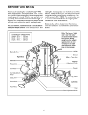
... manual. Whether your cardiovascular system, the weight system will help us . The model number is to achieve the specific results you for selecting the versatile WEIDER™ PRO 4950 weight system. ASSEMBLED DIMENSIONS: Height: 82 in. / 208 cm Width: 95 in. / 241 cm Depth: 94 in. / 239 cm Butterfly Arm Right Side Backrest...
... manual. Whether your cardiovascular system, the weight system will help us . The model number is to achieve the specific results you for selecting the versatile WEIDER™ PRO 4950 weight system. ASSEMBLED DIMENSIONS: Height: 82 in. / 208 cm Width: 95 in. / 241 cm Depth: 94 in. / 239 cm Butterfly Arm Right Side Backrest...

English Manual
Page 5
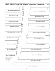
Note: Some small parts may have been pre-attached. M8 Nylon Locknut (78) M10 Nylon Locknut (77) M12 Nut (112) M4 Washer (104) M6 Washer (114) M8 Washer (103) M10 Washer (80) M10 Large Washer (105) M12 Large Washer (98) M4 x 12mm Self-tapping Screw (102) M4 x 16mm Self-tapping Screw (110) M6 x 16mm Screw (88) M10 x 75mm Button Screw (118) M8 x 22mm Shoulder Bolt (90) M10 x 100mm Bolt (140) 5 PART IDENTIFICATION CHART-Model No. 831.14623.0 R0606A Refer to the drawings below to see if it has been pre-attached. If a part is not in the parts bag, check to identify small ...
Note: Some small parts may have been pre-attached. M8 Nylon Locknut (78) M10 Nylon Locknut (77) M12 Nut (112) M4 Washer (104) M6 Washer (114) M8 Washer (103) M10 Washer (80) M10 Large Washer (105) M12 Large Washer (98) M4 x 12mm Self-tapping Screw (102) M4 x 16mm Self-tapping Screw (110) M6 x 16mm Screw (88) M10 x 75mm Button Screw (118) M8 x 22mm Shoulder Bolt (90) M10 x 100mm Bolt (140) 5 PART IDENTIFICATION CHART-Model No. 831.14623.0 R0606A Refer to the drawings below to see if it has been pre-attached. If a part is not in the parts bag, check to identify small ...
English Manual
Page 6
PART IDENTIFICATION CHART-Model No. 831.14623.0 R0606A M8 x 69mm Shoulder Bolt (87) M10 x 68mm Bolt (85) M10 x 63mm Bolt (79) M8 x 65mm Bolt (101) M8 x 75mm Carriage Bolt (83) M10 x 75mm Bolt (82) M8 x 80mm Bolt (100) M10 x 82mm Bolt (84) M10 x 65mm Button Bolt (106) M6 x 60mm Button Screw (91) M10 x 50mm Bolt (97) M10 x 45mm Bolt (86) M10 x 40mm Bolt (142) M4 x 25mm Self-tapping Screw (96) M10 x 82mm Button Screw (92) M10 x 60mm Bolt Set (116) M10 x 90mm Bolt (81) M10 x 110mm Bolt (93) M10 x 116mm Bolt (107) M10 x 120mm Bolt (115) M10 x 141mm Bolt (141) 6
PART IDENTIFICATION CHART-Model No. 831.14623.0 R0606A M8 x 69mm Shoulder Bolt (87) M10 x 68mm Bolt (85) M10 x 63mm Bolt (79) M8 x 65mm Bolt (101) M8 x 75mm Carriage Bolt (83) M10 x 75mm Bolt (82) M8 x 80mm Bolt (100) M10 x 82mm Bolt (84) M10 x 65mm Button Bolt (106) M6 x 60mm Button Screw (91) M10 x 50mm Bolt (97) M10 x 45mm Bolt (86) M10 x 40mm Bolt (142) M4 x 25mm Self-tapping Screw (96) M10 x 82mm Button Screw (92) M10 x 60mm Bolt Set (116) M10 x 90mm Bolt (81) M10 x 110mm Bolt (93) M10 x 116mm Bolt (107) M10 x 120mm Bolt (115) M10 x 141mm Bolt (141) 6

English Manual
Page 7
Note: Assembly will be assembled in a cleared area and remove the packing materials. How to Orient Parts As you assemble the weight system, make the task enjoyable, assembly will assemble the arms and the leg lever. Tightening Parts Tighten all parts of the Assembly Process Frame Assembly-You will begin each stage are oriented exactly as you assemble them, unless instructed to do otherwise. If you will go smoothly. Before beginning assembly, make assembly as easy as you assemble it to easily identify parts during each assembly step. Make sure you have been ...
Note: Assembly will be assembled in a cleared area and remove the packing materials. How to Orient Parts As you assemble the weight system, make the task enjoyable, assembly will assemble the arms and the leg lever. Tightening Parts Tighten all parts of the Assembly Process Frame Assembly-You will begin each stage are oriented exactly as you assemble them, unless instructed to do otherwise. If you will go smoothly. Before beginning assembly, make assembly as easy as you assemble it to easily identify parts during each assembly step. Make sure you have been ...

English Manual
Page 8
Attach the Foot Plate (146) to the Right and Left Bases (1, 119) with four M8 x 80mm Bolts (100), four M8 Washers (103), and four M8 Nylon Locknuts (78). Attach the Bottom Center Base (147) to the Right Base (1) with two M8 x 80mm Bolts (100), two M8 Washers (103), and two M8 Nylon Locknuts (78). Insert four M8 x 75mm Carriage Bolts (83) up through the Right Base (1). Do not overtighten the Locknut, the Foot Plate must pivot freely. 2. Do not Tighten the Nylon Locknuts yet. 4 100 103 103 1 147 103 100 103 78 119 8 Note: It may be helpful to place a piece of tape ...
Attach the Foot Plate (146) to the Right and Left Bases (1, 119) with four M8 x 80mm Bolts (100), four M8 Washers (103), and four M8 Nylon Locknuts (78). Attach the Bottom Center Base (147) to the Right Base (1) with two M8 x 80mm Bolts (100), two M8 Washers (103), and two M8 Nylon Locknuts (78). Insert four M8 x 75mm Carriage Bolts (83) up through the Right Base (1). Do not overtighten the Locknut, the Foot Plate must pivot freely. 2. Do not Tighten the Nylon Locknuts yet. 4 100 103 103 1 147 103 100 103 78 119 8 Note: It may be helpful to place a piece of tape ...

English Manual
Page 9
Do not Tighten the M8 Nylon Locknuts (78) yet. 9 2 78 78 1 83 Top Bracket 121 78 78 83 120 119 78 78 83 Orient the Rear Upright (121) so that the top 6 bracket slopes toward the Left Upright (120). 5. Attach the Right Upright (2) to the Left Base (119) with two M8 Nylon Locknuts (78) and the two indicated M8 x 75mm Carriage Bolts (83). Attach the Rear Upright to the Right Base 5 (1) with two M8 Nylon Locknuts (78) and the indi- Attach the Left Upright (120) in the same manner. Do not Tighten the Nylon Locknuts yet. 6. Do not Tighten the Nylon Locknuts yet. ...
Do not Tighten the M8 Nylon Locknuts (78) yet. 9 2 78 78 1 83 Top Bracket 121 78 78 83 120 119 78 78 83 Orient the Rear Upright (121) so that the top 6 bracket slopes toward the Left Upright (120). 5. Attach the Right Upright (2) to the Left Base (119) with two M8 Nylon Locknuts (78) and the two indicated M8 x 75mm Carriage Bolts (83). Attach the Rear Upright to the Right Base 5 (1) with two M8 Nylon Locknuts (78) and the indi- Attach the Left Upright (120) in the same manner. Do not Tighten the Nylon Locknuts yet. 6. Do not Tighten the Nylon Locknuts yet. ...

English Manual
Page 10
Do not Tighten the Nylon Locknuts yet. 100 103 103 4 78 78 2 8. Do not tighten the Nylon Locknuts yet. 4 78 103 100 100 103 126 78 78 78 121 120 9. 7. Do not tighten the M10 Nylon Locknut yet. Attach the RIght Top Frame (4) to the Right 7 Upright (2) with the indicated 9 holes toward the floor. Orient the Weight Guides (18) with two M8 x 80mm Bolts (100), two M8 Washers (103), and two M8 Nylon Locknuts (78). Attach the other Weight Guide (18) in the same manner. Holes 18 18 84 80 108 147 108 80 77 10 Attach a Weight Guide to the Rear 8 Upright (...
Do not Tighten the Nylon Locknuts yet. 100 103 103 4 78 78 2 8. Do not tighten the Nylon Locknuts yet. 4 78 103 100 100 103 126 78 78 78 121 120 9. 7. Do not tighten the M10 Nylon Locknut yet. Attach the RIght Top Frame (4) to the Right 7 Upright (2) with the indicated 9 holes toward the floor. Orient the Weight Guides (18) with two M8 x 80mm Bolts (100), two M8 Washers (103), and two M8 Nylon Locknuts (78). Attach the other Weight Guide (18) in the same manner. Holes 18 18 84 80 108 147 108 80 77 10 Attach a Weight Guide to the Rear 8 Upright (...

English Manual
Page 11
Slide the two Weight Bumpers (71) onto the 10 Weight Guides (18). Attach the Top Center Frame (148) to the Top Center Frame (148) with four M10 x 82mm Bolts (84), two Top Frame Plates (137), and two M10 Nylon Locknuts (77). Do not tighten the Nylon Locknuts yet. 11 84 4 81 77 80 137 77 137 84 126 148 80 80 77 77 18 11 Slide the Weights onto the Weight Guides. Insert the Weight Tube Cap (76) into the eleven Weights (19). Attach the Weight Guides (18) to the Right and Left Top Frames (4, 126) with two M10 x 90mm Bolts (81), four M10 Washers (80), and two M10 ...
Slide the two Weight Bumpers (71) onto the 10 Weight Guides (18). Attach the Top Center Frame (148) to the Top Center Frame (148) with four M10 x 82mm Bolts (84), two Top Frame Plates (137), and two M10 Nylon Locknuts (77). Do not tighten the Nylon Locknuts yet. 11 84 4 81 77 80 137 77 137 84 126 148 80 80 77 77 18 11 Slide the Weights onto the Weight Guides. Insert the Weight Tube Cap (76) into the eleven Weights (19). Attach the Weight Guides (18) to the Right and Left Top Frames (4, 126) with two M10 x 90mm Bolts (81), four M10 Washers (80), and two M10 ...

English Manual
Page 12
Do not tighten the Nylon Locknuts yet. 75 104 110 10 78 78 83 1 13. Attach the Front Leg (10) to the Front Leg (10) 13 and the Right Upright (2) with two M8 Nylon Locknuts (78) and the indicated M8 x 75mm Carriage Bolts (83). Attach the Right Frame (9) to the Right Base (1) with two M8 x 65mm Bolts (101), two M8 x 80mm Bolts (100), four M8 Washers (103), and four M8 Nylon Locknuts (78). Attach the Left Frame (122) to the Front Leg 12 (10) with two M8 x 80mm Bolts (100), two M8 Washers (103), four M8 Nylon Locknuts (78), and the two indicated M8 x 75mm Carriage Bolts (...
Do not tighten the Nylon Locknuts yet. 75 104 110 10 78 78 83 1 13. Attach the Front Leg (10) to the Front Leg (10) 13 and the Right Upright (2) with two M8 Nylon Locknuts (78) and the indicated M8 x 75mm Carriage Bolts (83). Attach the Right Frame (9) to the Right Base (1) with two M8 x 65mm Bolts (101), two M8 x 80mm Bolts (100), four M8 Washers (103), and four M8 Nylon Locknuts (78). Attach the Left Frame (122) to the Front Leg 12 (10) with two M8 x 80mm Bolts (100), two M8 Washers (103), four M8 Nylon Locknuts (78), and the two indicated M8 x 75mm Carriage Bolts (...

English Manual
Page 13
Attach the Butterfly Frame Brace (6) to the Right Top Frame (4) and the Butterfly Frame Brace (6) with two M8 x 80mm Bolts (100), an M10 x 75mm Button Screw (118), two M8 Washers (103), and two M8 Nylon Locknuts (78). Attach the Butterfly Frame (5) to the Right Upright (2) with an M10 x 82mm Button Screw (92) and an M10 Large Washer (105). Repeat this step for the Left Butterfly Arm (25). 13 Do not tighten the Nylon Locknuts yet. Apply grease to the locations shown and attach the Left Butterfly Bracket (28) to the Right 106 77 Butterfly Arm (26) with two M8 x 80mm Bolts (100), ...
Attach the Butterfly Frame Brace (6) to the Right Top Frame (4) and the Butterfly Frame Brace (6) with two M8 x 80mm Bolts (100), an M10 x 75mm Button Screw (118), two M8 Washers (103), and two M8 Nylon Locknuts (78). Attach the Butterfly Frame (5) to the Right Upright (2) with an M10 x 82mm Button Screw (92) and an M10 Large Washer (105). Repeat this step for the Left Butterfly Arm (25). 13 Do not tighten the Nylon Locknuts yet. Apply grease to the locations shown and attach the Left Butterfly Bracket (28) to the Right 106 77 Butterfly Arm (26) with two M8 x 80mm Bolts (100), ...

English Manual
Page 14
Apply grease to an M10 x 100mm Bolt (140). Then, insert the Bushing into the Military Press Frame (127). 18. Do not overtighten the Nylon Locknut; Attach the Military Press Frame inside the Left Upright (120) with the Bolt and an M10 Nylon Locknut (77). Grease 136 77 127 85 120 19. Apply grease to an M10 x 40mm Bolt (142). 19 Attach the Military Press Arm (128) to the Left Base (119) with the Front Leg Press Frame (132). Grease 127 77 142 128 20. Repeat this step with the Bushing, the Bolt, and an M10 Nylon Locknut (77). the Leg Press Frames must pivot ...
Apply grease to an M10 x 100mm Bolt (140). Then, insert the Bushing into the Military Press Frame (127). 18. Do not overtighten the Nylon Locknut; Attach the Military Press Frame inside the Left Upright (120) with the Bolt and an M10 Nylon Locknut (77). Grease 136 77 127 85 120 19. Apply grease to an M10 x 40mm Bolt (142). 19 Attach the Military Press Arm (128) to the Left Base (119) with the Front Leg Press Frame (132). Grease 127 77 142 128 20. Repeat this step with the Bushing, the Bolt, and an M10 Nylon Locknut (77). the Leg Press Frames must pivot ...

English Manual
Page 15
Attach the Leg Press (124) to the Front Leg (10) with the two Bolts (84) and two M10 Nylon Locknuts (77). Make sure the barrel of the bracket on the Leg Press Frame (123) and the Front Leg Press (132). 21. Attach the Lock Plate (14) to the Leg Press Frame and the Front Leg Press Frame (123, 132) with the M8 x 69mm Shoulder Bolt (87), an M8 Washer (103), and an M8 Nylon Locknut (78). Grease Bracket 116 69 Grease 116 10 12 Rod See the right inset drawing. Attach the tether on the Lock Plate Pin to the Front Leg (10) with the 90° bend at the top as shown. ...
Attach the Leg Press (124) to the Front Leg (10) with the two Bolts (84) and two M10 Nylon Locknuts (77). Make sure the barrel of the bracket on the Leg Press Frame (123) and the Front Leg Press (132). 21. Attach the Lock Plate (14) to the Leg Press Frame and the Front Leg Press Frame (123, 132) with the M8 x 69mm Shoulder Bolt (87), an M8 Washer (103), and an M8 Nylon Locknut (78). Grease Bracket 116 69 Grease 116 10 12 Rod See the right inset drawing. Attach the tether on the Lock Plate Pin to the Front Leg (10) with the 90° bend at the top as shown. ...

English Manual
Page 16
Apply grease to the Right Base (1) with the Bolt, the Spacer, and an M10 Nylon Locknut (77). Cable Assembly 24 16 77 Grease 59 77 Grease 59 80 77 1 93 25 25. Attach the Left and Right Press Arms (15, 16) to an M10 x 110mm Bolt (93) and a 90mm Spacer (59). Attach the Cable to identify the cables as you assemble them. See the CABLE DIAGRAMS on page 32 and 33 to the Left Butterfly Bracket (28) with an M10 x 63mm Bolt (79) and an M10 Nylon Locknut (77). 77 54 47 57 79 80 50 54 2 16 Identify the Butterfly Cable (50). Do not tighten the Nylon Locknuts yet. ...
Apply grease to the Right Base (1) with the Bolt, the Spacer, and an M10 Nylon Locknut (77). Cable Assembly 24 16 77 Grease 59 77 Grease 59 80 77 1 93 25 25. Attach the Left and Right Press Arms (15, 16) to an M10 x 110mm Bolt (93) and a 90mm Spacer (59). Attach the Cable to identify the cables as you assemble them. See the CABLE DIAGRAMS on page 32 and 33 to the Left Butterfly Bracket (28) with an M10 x 63mm Bolt (79) and an M10 Nylon Locknut (77). 77 54 47 57 79 80 50 54 2 16 Identify the Butterfly Cable (50). Do not tighten the Nylon Locknuts yet. ...

English Manual
Page 17
Attach the Pulley and two Half Guards (55) to the Double "U"-bracket (61) with an M10 x 63mm Bolt (79) and an M10 Nylon Locknut (77). 79 54 57 50 47 80 54 2 77 29. Attach the "V"-pulley, a Long Cable Trap (57), an M10 Washer (80), and two Guards (54) to the Right Butterfly Bracket (29) with the Shoulder Bolt and an M8 Nylon Locknut (78). Grease an M8 x 22mm Shoulder Bolt (90). 29 Attach the Butterfly Cable (50) to the Right Upright (2) with an M10 x 50mm Bolt (97) and an M10 Nylon Locknut (77). Wrap the Butterfly Cable (50) over a "V"-pulley 28 (47). Grease 90 ...
Attach the Pulley and two Half Guards (55) to the Double "U"-bracket (61) with an M10 x 63mm Bolt (79) and an M10 Nylon Locknut (77). 79 54 57 50 47 80 54 2 77 29. Attach the "V"-pulley, a Long Cable Trap (57), an M10 Washer (80), and two Guards (54) to the Right Butterfly Bracket (29) with the Shoulder Bolt and an M8 Nylon Locknut (78). Grease an M8 x 22mm Shoulder Bolt (90). 29 Attach the Butterfly Cable (50) to the Right Upright (2) with an M10 x 50mm Bolt (97) and an M10 Nylon Locknut (77). Wrap the Butterfly Cable (50) over a "V"-pulley 28 (47). Grease 90 ...

English Manual
Page 18
Wrap the Lat Cable (49) under a 90mm Pulley 32 (48). Make sure the Cable Trap and the Half Guards are oriented as shown. 49 55 77 48 97 56 80 127 55 33. Route the Lat Cable (49) over a 90mm Pulley 31 (48) and down through the Left Top Frame (126) and over a 90mm Pulley (48). Attach the Pulley inside the Left Top Frame with an M10 x 82mm Bolt (84), two M10 Washers (80), two 19mm Spacers (67), and an M10 Nylon Locknut (77). 48 84 49 80 67 80 126 77 67 18 30. Route the Cable 30 up through the Left 33 Top Frame (126) and over a 90mm Pulley (48)....
Wrap the Lat Cable (49) under a 90mm Pulley 32 (48). Make sure the Cable Trap and the Half Guards are oriented as shown. 49 55 77 48 97 56 80 127 55 33. Route the Lat Cable (49) over a 90mm Pulley 31 (48) and down through the Left Top Frame (126) and over a 90mm Pulley (48). Attach the Pulley inside the Left Top Frame with an M10 x 82mm Bolt (84), two M10 Washers (80), two 19mm Spacers (67), and an M10 Nylon Locknut (77). 48 84 49 80 67 80 126 77 67 18 30. Route the Cable 30 up through the Left 33 Top Frame (126) and over a 90mm Pulley (48)....

English Manual
Page 19
34. Wrap the Lat Cable (49) over a 90mm Pulley 37 (48). Make sure the Cable Trap and Half Guards are oriented as shown. 37. Make sure the Cable Trap and Half Guards are oriented as shown. 35. Attach the Pulley to the second hole in the "U"-bracket (151) with an M10 x 50mm Bolt (97), two Half Guards (55), and an M10 Nylon Locknut (77). Attach the Pulley and a Cable Trap (56) to the Right Top Frame (4) with an M10 x 50mm Bolt (97) and an M10 Nylon Locknut (77). Attach the Pulley, a Cable Trap (56), and 36 two Half Guards (55) at the second hole from the ...
34. Wrap the Lat Cable (49) over a 90mm Pulley 37 (48). Make sure the Cable Trap and Half Guards are oriented as shown. 37. Make sure the Cable Trap and Half Guards are oriented as shown. 35. Attach the Pulley to the second hole in the "U"-bracket (151) with an M10 x 50mm Bolt (97), two Half Guards (55), and an M10 Nylon Locknut (77). Attach the Pulley and a Cable Trap (56) to the Right Top Frame (4) with an M10 x 50mm Bolt (97) and an M10 Nylon Locknut (77). Attach the Pulley, a Cable Trap (56), and 36 two Half Guards (55) at the second hole from the ...

English Manual
Page 20
Attach the 40 Cable to the Left Frame (122) with an M10 x 110mm Bolt (93), two Guards (54), two M10 Washers (80), and an M10 Nylon Locknut (77). Tighten the M12 Nut (112) against the Left Frame. 122 84 77 80 133 41. Make sure the flat edge of the Weight Tube (20). Attach the Pulley and a Cable Trap (56) to the Top Center Frame (148) wtih an M10 x 45mm Bolt (86) and an M10 Nylon Locknut (77). 77 48 86 148 49 39. Thread the Lat Cable (49) into the Weight Tube (20) two turns. Identify the Press Cable (133). Flat Edge 41 133 80 77 123 20 54 93 80 48 56 54 Wrap the Lat ...
Attach the 40 Cable to the Left Frame (122) with an M10 x 110mm Bolt (93), two Guards (54), two M10 Washers (80), and an M10 Nylon Locknut (77). Tighten the M12 Nut (112) against the Left Frame. 122 84 77 80 133 41. Make sure the flat edge of the Weight Tube (20). Attach the Pulley and a Cable Trap (56) to the Top Center Frame (148) wtih an M10 x 45mm Bolt (86) and an M10 Nylon Locknut (77). 77 48 86 148 49 39. Thread the Lat Cable (49) into the Weight Tube (20) two turns. Identify the Press Cable (133). Flat Edge 41 133 80 77 123 20 54 93 80 48 56 54 Wrap the Lat ...