

English Manual
Page 2
... for foot protection. 13. Important Precautions WARNING: To reduce the risk of serious injury, read the following important precautions before beginning assembly. Table of Contents IMPORTANT PRECAUTIONS 2 BEFORE YOU BEGIN 3 ASSEMBLY 4 HOW TO USE THE HOME GYM SYSTEM 22 WEIGHT RESISTANCE CHART 24 TROUBLE-SHOOTING AND MAINTENANCE 25 CABLE DIAGRAMS 26 ORDERING...
... for foot protection. 13. Important Precautions WARNING: To reduce the risk of serious injury, read the following important precautions before beginning assembly. Table of Contents IMPORTANT PRECAUTIONS 2 BEFORE YOU BEGIN 3 ASSEMBLY 4 HOW TO USE THE HOME GYM SYSTEM 22 WEIGHT RESISTANCE CHART 24 TROUBLE-SHOOTING AND MAINTENANCE 25 CABLE DIAGRAMS 26 ORDERING...

English Manual
Page 3
...ASSEMBLED DIMENSIONS: Height: 78 in . Whether your goal is to achieve the specific results you have additional questions, please call our Customer Service Department toll-free at 1-800-9993756, Monday through Friday, 6 a.m. For your cardiovascular system, the WEIDER¨ PRO 9925 will help us assist you for selecting the versatile WEIDER¨ PRO 9925...You Begin Thank you , please note the product model number and serial number before using the WEIDER¨ PRO 9925 Training System. until 6 p.m. Apply the replacement decal to order a replacement decal. Mountain ...
...ASSEMBLED DIMENSIONS: Height: 78 in . Whether your goal is to achieve the specific results you have additional questions, please call our Customer Service Department toll-free at 1-800-9993756, Monday through Friday, 6 a.m. For your cardiovascular system, the WEIDER¨ PRO 9925 will help us assist you for selecting the versatile WEIDER¨ PRO 9925...You Begin Thank you , please note the product model number and serial number before using the WEIDER¨ PRO 9925 Training System. until 6 p.m. Apply the replacement decal to order a replacement decal. Mountain ...

English Manual
Page 4
...table and use it takes to open the parts bag labeled for Yourself Everything in the shipping box. Assembly will later be sure that assembly stage. Seat Assembly Completes the seat and backrest that connect the moving parts will be completed successfully by deciding to walk ...all moving arms with the weights. Most people find that the assembly of this manual is completed. ¥ One (1) phillips screwdriver ¥ One (1) rubber mallet ¥ Lubricant, such as grease or ...
...table and use it takes to open the parts bag labeled for Yourself Everything in the shipping box. Assembly will later be sure that assembly stage. Seat Assembly Completes the seat and backrest that connect the moving parts will be completed successfully by deciding to walk ...all moving arms with the weights. Most people find that the assembly of this manual is completed. ¥ One (1) phillips screwdriver ¥ One (1) rubber mallet ¥ Lubricant, such as grease or ...
English Manual
Page 5
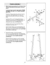
Before beginning assembly, be sure that you have read and understand the information in the Weight Base (14). Press a 2Ó Square Inner Cap (56) into the end of ... not tighten the Nylon Locknuts yet. Locate and open the parts bags labeled ÒFRAME ASSEMBLY BAG ONEÓ and ÒFRAME ASSEMBLY BAG TWO.Ó Press two 2Ó Square Outer Caps (58) onto the indi- FRAME ASSEMBLY 1 1. cated ends of the Weight Base. 14 Insert two 5/16Ó x 2 1/2Ó Carriage Bolts (49...
Before beginning assembly, be sure that you have read and understand the information in the Weight Base (14). Press a 2Ó Square Inner Cap (56) into the end of ... not tighten the Nylon Locknuts yet. Locate and open the parts bags labeled ÒFRAME ASSEMBLY BAG ONEÓ and ÒFRAME ASSEMBLY BAG TWO.Ó Press two 2Ó Square Outer Caps (58) onto the indi- FRAME ASSEMBLY 1 1. cated ends of the Weight Base. 14 Insert two 5/16Ó x 2 1/2Ó Carriage Bolts (49...
English Manual
Page 9
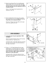
... (42). 8 9 53 72 13 42 98ÑLubricate 16. 13. Locate and open ends of the Leg Press Arm (9). 14 73 9 10 11 56 ARM ASSEMBLY 15 15. Attach the Leg Press Plate (11) to the Press Base (13) with a 5/16Ó x 2 1/2Ó Bolt (39), two 5/16Ó Washers (20) and... that the high hole is oriented as shown. 13 48 Press a 1 3/4Ó Square Inner Cap (48) into the open the parts bag labeled ÒARM ASSEMBLY.Ó Attach the Leg Press Bumper (53) to the Press Base (13) with the Lock Pin (73).
... (42). 8 9 53 72 13 42 98ÑLubricate 16. 13. Locate and open ends of the Leg Press Arm (9). 14 73 9 10 11 56 ARM ASSEMBLY 15 15. Attach the Leg Press Plate (11) to the Press Base (13) with a 5/16Ó x 2 1/2Ó Bolt (39), two 5/16Ó Washers (20) and... that the high hole is oriented as shown. 13 48 Press a 1 3/4Ó Square Inner Cap (48) into the open the parts bag labeled ÒARM ASSEMBLY.Ó Attach the Leg Press Bumper (53) to the Press Base (13) with the Lock Pin (73).
English Manual
Page 10
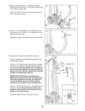
Attach the other Press Arm (not shown). 40 7 12 48 80 7 19. Lubricate both axles on the Butterfly Frame (3). IMPORTANT NOTE: Before assembling the 1Ó Retainers (45) used in this step for the other Press Arm (7) to the Press Frame (12) in the same manner. 39 7 18. Tap ... 10 Press a 1 3/4Ó Square Inner Cap (48) into the upper end of the Press 17 Frame (12) with the Right Arm (5). Repeat this step, be assembled only once.
Attach the other Press Arm (not shown). 40 7 12 48 80 7 19. Lubricate both axles on the Butterfly Frame (3). IMPORTANT NOTE: Before assembling the 1Ó Retainers (45) used in this step for the other Press Arm (7) to the Press Frame (12) in the same manner. 39 7 18. Tap ... 10 Press a 1 3/4Ó Square Inner Cap (48) into the upper end of the Press 17 Frame (12) with the Right Arm (5). Repeat this step, be assembled only once.
English Manual
Page 11
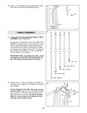
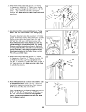
... identify the Cables by comparing the lengths and the ends. Slide one end of the Left Arm (6) and the Right Arm (5). 20 5 6 48 48 CABLE ASSEMBLY 21 21. Thread another 5/16Ó Nylon Jam Nut (91) onto the Bolt, but do not overtighten the bolts and nuts attaching the pulleys. Tighten.... Leave enough room between the two Jam Nuts for the Cable to turn freely. 22. IMPORTANT: While assembling the cables, do not fully tighten it. Locate and open the parts bags labeled ÒCABLE ASSEMBLYÓ and ÒPULLEYS.Ó During steps 19 through the bracket on pages 26 and 27 of...
... identify the Cables by comparing the lengths and the ends. Slide one end of the Left Arm (6) and the Right Arm (5). 20 5 6 48 48 CABLE ASSEMBLY 21 21. Thread another 5/16Ó Nylon Jam Nut (91) onto the Bolt, but do not overtighten the bolts and nuts attaching the pulleys. Tighten.... Leave enough room between the two Jam Nuts for the Cable to turn freely. 22. IMPORTANT: While assembling the cables, do not fully tighten it. Locate and open the parts bags labeled ÒCABLE ASSEMBLYÓ and ÒPULLEYS.Ó During steps 19 through the bracket on pages 26 and 27 of...
English Manual
Page 12
... a 5/16Ó x 1Ó Bolt (97) through the bracket on Cable 94 82 25. Make sure the Cable Trap is oriented as shown in the following assembly steps. Attach the ÒVÓ Pulley to pivot. 12
... a 5/16Ó x 1Ó Bolt (97) through the bracket on Cable 94 82 25. Make sure the Cable Trap is oriented as shown in the following assembly steps. Attach the ÒVÓ Pulley to pivot. 12
English Manual
Page 20
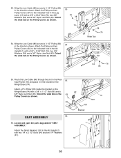
...with a 3/8Ó x 3 3/4Ó Bolt (76), two 3/8Ó Washers (38) and a 3/8Ó Nylon Jam Nut (43). Attach a Pro Pulley (62) inside the bracket on the 43 Pulley Covers as shown. 86 SEAT ASSEMBLY 56 56. Orient the wide tab on the Weight Base (14) with two 1/4Ó x 2 1/2Ó Bolts (64) and... Ab Upright (1) with a 3/8Ó x 1 1/2Ó Bolt (66) and a 3/8Ó Nylon Jam Nut (43). Locate and open the parts bag labeled ÒSEAT ASSEMBLY.Ó Attach the Small Backrest (18) to the indicated hole in the direction shown. Orient the wide tab on the Weight Base (14). Route the...
...with a 3/8Ó x 3 3/4Ó Bolt (76), two 3/8Ó Washers (38) and a 3/8Ó Nylon Jam Nut (43). Attach a Pro Pulley (62) inside the bracket on the 43 Pulley Covers as shown. 86 SEAT ASSEMBLY 56 56. Orient the wide tab on the Weight Base (14) with two 1/4Ó x 2 1/2Ó Bolts (64) and... Ab Upright (1) with a 3/8Ó x 1 1/2Ó Bolt (66) and a 3/8Ó Nylon Jam Nut (43). Locate and open the parts bag labeled ÒSEAT ASSEMBLY.Ó Attach the Small Backrest (18) to the indicated hole in the direction shown. Orient the wide tab on the Weight Base (14). Route the...
English Manual
Page 26
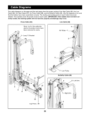
... Cable (85), the Low Cable (86), the Rear Cable (87), the Press Cable (88), and the Butterfly Cable (89). IMPORTANT: If the Cables have been assembled correctly. The numbers show the proper routing of each Cable. Press Cable (88) Low Cable (86) Note: In all of the cable diagrams, the pulley...
... Cable (85), the Low Cable (86), the Rear Cable (87), the Press Cable (88), and the Butterfly Cable (89). IMPORTANT: If the Cables have been assembled correctly. The numbers show the proper routing of each Cable. Press Cable (88) Low Cable (86) Note: In all of the cable diagrams, the pulley...


