
English Manual
Page 2
.... WARNING: Before beginning this manual. tions before using the home gym. 3. Make sure the cables remain on all instructions before beginning assembly. Replace any worn parts immediately. 6. The home gym is the responsibility of the owner to ensure that could cause the home gym to... arms, leg lever, lat bar or ab strap while weights are raised. Table of Contents Important Precautions 2 Before You Begin 3 Assembly 4 Cable Diagrams 23 Adjustment 25 Trouble-shooting and Maintenance 26 Weight Resistance Chart 27 Ordering Replacement Parts Back Cover Full 90-day Warranty...
.... WARNING: Before beginning this manual. tions before using the home gym. 3. Make sure the cables remain on all instructions before beginning assembly. Replace any worn parts immediately. 6. The home gym is the responsibility of the owner to ensure that could cause the home gym to... arms, leg lever, lat bar or ab strap while weights are raised. Table of Contents Important Precautions 2 Before You Begin 3 Assembly 4 Cable Diagrams 23 Adjustment 25 Trouble-shooting and Maintenance 26 Weight Resistance Chart 27 Ordering Replacement Parts Back Cover Full 90-day Warranty...

English Manual
Page 3
... decal attached to the WEIDER® PRO 9940 Home Gym (see the front cover of the body. until 7 p.m. Central Time (excluding holidays). The model number is to tone your body, build dramatic muscle size and strength or improve your benefit, read this manual). ASSEMBLED DIMENSIONS: Height: 77 in... you , please note the product model number and serial number before using the WEIDER® PRO 9940 Home Gym. Width: 80 in . If you for selecting the innovative and versatile WEIDER® PRO 9940 Home Gym. Before You Begin Thank you have additional questions, please call our ...
... decal attached to the WEIDER® PRO 9940 Home Gym (see the front cover of the body. until 7 p.m. Central Time (excluding holidays). The model number is to tone your body, build dramatic muscle size and strength or improve your benefit, read this manual). ASSEMBLED DIMENSIONS: Height: 77 in... you , please note the product model number and serial number before using the WEIDER® PRO 9940 Home Gym. Width: 80 in . If you for selecting the innovative and versatile WEIDER® PRO 9940 Home Gym. Before You Begin Thank you have additional questions, please call our ...

English Manual
Page 4
... is designed to open -end or closed-end wrenches or a set of the equipment. However, it ! Arm Assembly This assembly completes the press and butterfly arms that assembly stage. • One (1) rubber mallet • Lubricant, such as grease or petroleum jelly, and soapy water ... deciding to complete the steps outlined here. Do not dispose of evenings. Orienting Parts As you are exercising. 4 Lining Up the Tools Assembly requires the following tools (not included): • Two (2) adjustable wrenches • One (1) standard screwdriver • One (1) phillips screwdriver...
... is designed to open -end or closed-end wrenches or a set of the equipment. However, it ! Arm Assembly This assembly completes the press and butterfly arms that assembly stage. • One (1) rubber mallet • Lubricant, such as grease or petroleum jelly, and soapy water ... deciding to complete the steps outlined here. Do not dispose of evenings. Orienting Parts As you are exercising. 4 Lining Up the Tools Assembly requires the following tools (not included): • Two (2) adjustable wrenches • One (1) standard screwdriver • One (1) phillips screwdriver...
English Manual
Page 5
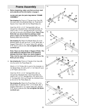
... 28 28 5 28 1b 89 93 64 64 4 5 2a 5 24 63 57 57 63 28 6 92 102 92 101 2b 64 5 64 93 6 89 5 Frame Assembly 1. Before beginning, make sure that will fit over the head of each end of the Butterfly Base (4). Place the Butterfly Base flat on the Weight... yet. Note: There are using. 2. See drawing 2a. Attach a 3 1/2" Pulley (24) to each of the Press Base (6). Locate and open the parts bag labeled "FRAME ASSEMBLY." Press two 2" Square Inner Caps (28) into each Bolt. Press a 2" Square Inner Cap (28) into the end of the Butterfly Base. See drawing 2b. Insert...
... 28 28 5 28 1b 89 93 64 64 4 5 2a 5 24 63 57 57 63 28 6 92 102 92 101 2b 64 5 64 93 6 89 5 Frame Assembly 1. Before beginning, make sure that will fit over the head of each end of the Butterfly Base (4). Place the Butterfly Base flat on the Weight... yet. Note: There are using. 2. See drawing 2a. Attach a 3 1/2" Pulley (24) to each of the Press Base (6). Locate and open the parts bag labeled "FRAME ASSEMBLY." Press two 2" Square Inner Caps (28) into each Bolt. Press a 2" Square Inner Cap (28) into the end of the Butterfly Base. See drawing 2b. Insert...
English Manual
Page 10
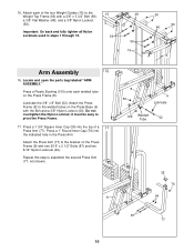
... Press Arm. Press a 1 3/4" Square Inner Cap (35) into the indicated hole in steps 1 through 15. 15 59 48 59 15 50 50 48 15 Arm Assembly 16 16. Lubricate the 3/8" x 8" Bolt (52). Attach the Press Arm (77) to the bracket on the Press Base (6) with a 3/8" x 3 3/4" Bolt (59), a 3/8" Flat Washer (48),... Press Arm (77). Attach each welded tube on the Press Frame (8). Repeat this step to pivot the Press Frame. 17. it must be easy to assemble the second Press Arm (77, not shown). 8 8 50 6 Lubricate 100 Welded Tube 52 35 76 64 87 77 10 Attach the Press Frame (8) ...
... Press Arm. Press a 1 3/4" Square Inner Cap (35) into the indicated hole in steps 1 through 15. 15 59 48 59 15 50 50 48 15 Arm Assembly 16 16. Lubricate the 3/8" x 8" Bolt (52). Attach the Press Arm (77) to the bracket on the Press Base (6) with a 3/8" x 3 3/4" Bolt (59), a 3/8" Flat Washer (48),... Press Arm (77). Attach each welded tube on the Press Frame (8). Repeat this step to pivot the Press Frame. 17. it must be easy to assemble the second Press Arm (77, not shown). 8 8 50 6 Lubricate 100 Welded Tube 52 35 76 64 87 77 10 Attach the Press Frame (8) ...

English Manual
Page 11
... 35 33 Axle 35 31 38 29 Cable Assembly 19. Remove one "V"-Pulley (27) from the bag. Make sure the Large Cable Trap is approximately 52" long and it onto the axle. Slide a Butterfly Foam Pad (29) onto the lower end of the Pro Pulley. Note: The loop on pages 23 and... on the Cable and the two Nylon Jamnuts must be mounted underneath the welded bracket. 20. Locate and open the parts bag labeled "CABLE 19 ASSEMBLY." Secure the Butterfly Arm with soapy water. Wrap the Butterfly Cable (73) around a "V"-Pulley (27) in the bag for identification of the Arm. It is...
... 35 33 Axle 35 31 38 29 Cable Assembly 19. Remove one "V"-Pulley (27) from the bag. Make sure the Large Cable Trap is approximately 52" long and it onto the axle. Slide a Butterfly Foam Pad (29) onto the lower end of the Pro Pulley. Note: The loop on pages 23 and... on the Cable and the two Nylon Jamnuts must be mounted underneath the welded bracket. 20. Locate and open the parts bag labeled "CABLE 19 ASSEMBLY." Secure the Butterfly Arm with soapy water. Wrap the Butterfly Cable (73) around a "V"-Pulley (27) in the bag for identification of the Arm. It is...

English Manual
Page 13
.... Attach the Pulley to the welded bracket on the Butterfly Base (4) with a 3/8" x 2" Bolt (54) and a 3/8" Nylon Locknut (50). Remove both 3 1/2" Pulleys (24) from the pre-assembled Adjustable Pulley Plates (23). Wrap the Ab Cable (74) around a 3 1/2" Pulley (24) in 27 the direction shown. Make sure the Pulley Bracket is oriented as...
.... Attach the Pulley to the welded bracket on the Butterfly Base (4) with a 3/8" x 2" Bolt (54) and a 3/8" Nylon Locknut (50). Remove both 3 1/2" Pulleys (24) from the pre-assembled Adjustable Pulley Plates (23). Wrap the Ab Cable (74) around a 3 1/2" Pulley (24) in 27 the direction shown. Make sure the Pulley Bracket is oriented as...

English Manual
Page 20
... (65). Secure the other end of the Press Backrest (99) with two 1/4" x 2 1/2" Bolts (79) and two 1/4" Flat Washers (71). 12 1 79 71 79 51. Seat Assembly 50 50. Locate and open the parts bag labeled "SEAT...
... (65). Secure the other end of the Press Backrest (99) with two 1/4" x 2 1/2" Bolts (79) and two 1/4" Flat Washers (71). 12 1 79 71 79 51. Seat Assembly 50 50. Locate and open the parts bag labeled "SEAT...

English Manual
Page 21
... (20). Insert the Pad Tube (42) into the indicated hole in the same manner. 52 13 45 65 14 49 71 68 71 79 Miscellaneous Assembly 53 43 30 Tube 53. Attach the Adjustment Tube (90) to the Curl Post (104) with the Lock Pin (91). Attach the Curl Pad (105...
... (20). Insert the Pad Tube (42) into the indicated hole in the same manner. 52 13 45 65 14 49 71 68 71 79 Miscellaneous Assembly 53 43 30 Tube 53. Attach the Adjustment Tube (90) to the Curl Post (104) with the Lock Pin (91). Attach the Curl Pad (105...

English Manual
Page 32
...the product (831.159730) • The NAME of the product (WEIDER® PRO 9940 Home Gym) • The KEY NUMBER and DESCRIPTION of your nearest SEARS Service Center. When requesting help assembling or operating the WEIDER® PRO 9940 Home Gym • a part is used commercially or for immediate purchase... Part No. 158051 R0800A Printed in the center of charge. This warranty gives you specific legal rights, and you visit your WEIDER® PRO 9940 Home Gym are available for rental purposes. Model No. 831.159730 QUESTIONS? All replacement parts are listed on a decal attached ...
...the product (831.159730) • The NAME of the product (WEIDER® PRO 9940 Home Gym) • The KEY NUMBER and DESCRIPTION of your nearest SEARS Service Center. When requesting help assembling or operating the WEIDER® PRO 9940 Home Gym • a part is used commercially or for immediate purchase... Part No. 158051 R0800A Printed in the center of charge. This warranty gives you specific legal rights, and you visit your WEIDER® PRO 9940 Home Gym are available for rental purposes. Model No. 831.159730 QUESTIONS? All replacement parts are listed on a decal attached ...


