Installation Instructions
Page 1
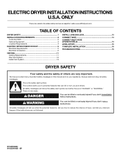
...una versión de estas instrucciones en español, visite www.Whirlpool.com TABLE OF CONTENTS DRYER SAFETY 1 INSTALLATION REQUIREMENTS 2 Tools and Parts 2 Optional Equipment 3 Location Requirements 3 ELECTRIC DRYER POWER HOOKUP 5 Electrical Requirements 5 Electrical Connection 6 VENTING 11 Venting ...CONNECT INLET HOSE (STEAM MODELS 14 LEVEL DRYER 15 COMPLETE INSTALLATION 15 TROUBLESHOOTING 15 DRYER SAFETY Your safety and the safety of injury, and tell you don't immediately follow instructions. ELECTRIC DRYER INSTALLATION INSTRUCTIONS U.S.A. All safety messages will ...
...una versión de estas instrucciones en español, visite www.Whirlpool.com TABLE OF CONTENTS DRYER SAFETY 1 INSTALLATION REQUIREMENTS 2 Tools and Parts 2 Optional Equipment 3 Location Requirements 3 ELECTRIC DRYER POWER HOOKUP 5 Electrical Requirements 5 Electrical Connection 6 VENTING 11 Venting ...CONNECT INLET HOSE (STEAM MODELS 14 LEVEL DRYER 15 COMPLETE INSTALLATION 15 TROUBLESHOOTING 15 DRYER SAFETY Your safety and the safety of injury, and tell you don't immediately follow instructions. ELECTRIC DRYER INSTALLATION INSTRUCTIONS U.S.A. All safety messages will ...

Installation Instructions
Page 2
...tools listed here. ■ Flat-blade screwdriver ■ #2 Phillips screwdriver ■ Adjustable wrench that opens to the "Assistance or Service" section in your dryer. Check that all parts are included. For further information, please refer to 1" (25 mm) or hex-head socket wrench (for adjusting... dryer feet) ■ Level ■ Wire stripper (direct wire installations) ■ Vent clamps ■ Caulking gun and compound (for purchase from the dealer ...
...tools listed here. ■ Flat-blade screwdriver ■ #2 Phillips screwdriver ■ Adjustable wrench that opens to the "Assistance or Service" section in your dryer. Check that all parts are included. For further information, please refer to 1" (25 mm) or hex-head socket wrench (for adjusting... dryer feet) ■ Level ■ Wire stripper (direct wire installations) ■ Vent clamps ■ Caulking gun and compound (for purchase from the dealer ...

Installation Instructions
Page 3
... mm) 31 1/2" (800 mm) 27" (686 mm) 51 1/2" (1308 mm) NOTE: Most installations require a minimum 5" (127 mm) clearance behind the dryer for your dryer. Optional Equipment Refer to your Use and Care guide for information about the accessories available for the exhaust vent with a maximum slope of 1" (25...times. If slope is no longer visible. 3 Clothes may not tumble properly and automatic sensor cycles may use the cold water supply from your dryer at the end of 20-100 psi (137.9-689.6 kPa). Do not operate your washer using a power supply cord, a grounded electrical outlet...
... mm) 31 1/2" (800 mm) 27" (686 mm) 51 1/2" (1308 mm) NOTE: Most installations require a minimum 5" (127 mm) clearance behind the dryer for your dryer. Optional Equipment Refer to your Use and Care guide for information about the accessories available for the exhaust vent with a maximum slope of 1" (25...times. If slope is no longer visible. 3 Clothes may not tumble properly and automatic sensor cycles may use the cold water supply from your dryer at the end of 20-100 psi (137.9-689.6 kPa). Do not operate your washer using a power supply cord, a grounded electrical outlet...

Installation Instructions
Page 4
...mm) 31 1/2" (800 mm) F** 5" (127 mm) 5" (127 mm) *Required spacing **For side or bottom venting, 0" (0 mm) spacing is no longer visible. Custom undercounter installation - Dryer only A B C* D E* Steam (Electric or Gas) Non-Steam (Electric or Gas) A 0" (0 mm) 0" (0 mm) B 38" (965 mm) 38" (965 mm) C* 1"... foot is allowed NOTE: Some models are acceptable. ■ Companion appliance spacing should be considered on all sides of the dryer to reduce noise transfer. ■ For closet installation, with a door, minimum ventilation openings in the top and bottom of...
...mm) 31 1/2" (800 mm) F** 5" (127 mm) 5" (127 mm) *Required spacing **For side or bottom venting, 0" (0 mm) spacing is no longer visible. Custom undercounter installation - Dryer only A B C* D E* Steam (Electric or Gas) Non-Steam (Electric or Gas) A 0" (0 mm) 0" (0 mm) B 38" (965 mm) 38" (965 mm) C* 1"... foot is allowed NOTE: Some models are acceptable. ■ Companion appliance spacing should be considered on all sides of the dryer to reduce noise transfer. ■ For closet installation, with a door, minimum ventilation openings in the top and bottom of...

Installation Instructions
Page 5
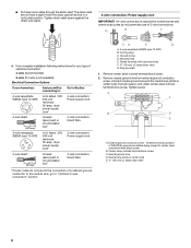
...your responsibility ■ To contact a qualified electrical installer. ■ To be at least twice as large as the dryer exhaust opening. Additional installation requirements This dryer is suitable for purchase from : National Fire Protection Association, One Batterymarch Park, Quincy, MA 02269. 5 Mobile home ... in mobile homes to the Manufactured Home Construction and Safety Standard, Title 24 CFR, Part 3280 (formerly the Federal Standard for homes built after 1996, dryer circuits involved in .2 * (155 cm2) 3"* (76 mm) 1"* (25 mm) A* 1" 27" 1" (25 mm) (686 mm) (25 mm)...
...your responsibility ■ To contact a qualified electrical installer. ■ To be at least twice as large as the dryer exhaust opening. Additional installation requirements This dryer is suitable for purchase from : National Fire Protection Association, One Batterymarch Park, Quincy, MA 02269. 5 Mobile home ... in mobile homes to the Manufactured Home Construction and Safety Standard, Title 24 CFR, Part 3280 (formerly the Federal Standard for homes built after 1996, dryer circuits involved in .2 * (155 cm2) 3"* (76 mm) 1"* (25 mm) A* 1" 27" 1" (25 mm) (686 mm) (25 mm)...

Installation Instructions
Page 6
...flexible metallic conduit. Disconnect power before making electrical connections. Failure to center terminal (silver). Electrical Connection To properly install your dryer, you will be removed from the external ground connector (green screw), and secured under the neutral terminal (center or white ... neutral wire, see "Optional 3-wire connection" section. ■ A 4-wire power supply connection must be connected to install with clothes dryers. The neutral ground conductor is manufactured ready to green ground connector. The cord should contain: ■ A UL listed 30-amp power...
...flexible metallic conduit. Disconnect power before making electrical connections. Failure to center terminal (silver). Electrical Connection To properly install your dryer, you will be removed from the external ground connector (green screw), and secured under the neutral terminal (center or white ... neutral wire, see "Optional 3-wire connection" section. ■ A 4-wire power supply connection must be connected to install with clothes dryers. The neutral ground conductor is manufactured ready to green ground connector. The cord should contain: ■ A UL listed 30-amp power...
Installation Instructions
Page 7
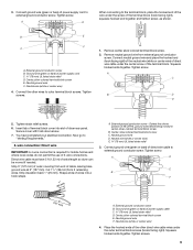
... mm) UL listed strain relief (UL marking on strain relief). Strain relief tab pointing down screw 3. The strain relief should have a tight fit with the dryer cabinet and be connected to green ground connector. Use a UL listed strain relief. Securely tighten all electrical connections. A B C A. Strain relief threads 7 C D B A A. Center, silver-colored terminal...
... mm) UL listed strain relief (UL marking on strain relief). Strain relief tab pointing down screw 3. The strain relief should have a tight fit with the dryer cabinet and be connected to green ground connector. Use a UL listed strain relief. Securely tighten all electrical connections. A B C A. Strain relief threads 7 C D B A A. Center, silver-colored terminal...
Installation Instructions
Page 8
...cabinet-ground conductor to the neutral wire, go to : 4-wire receptacle (NEMA Type 14-30R) A UL listed, 120/ 240-volt minimum, 30-amp, dryer power supply cord* 4-wire connection: Power supply cord 4-wire direct 5" (127 mm) 3-wire receptacle (NEMA type 10-30R) A fused disconnect or circuit ...breaker box* A UL listed, 120/ 240-volt minimum, 30-amp, dryer power supply cord* 4-wire connection: Direct Wire 3-wire connection: Power supply cord 3-wire direct (89 mm) A fused disconnect or circuit breaker box* 3-wire...
...cabinet-ground conductor to the neutral wire, go to : 4-wire receptacle (NEMA Type 14-30R) A UL listed, 120/ 240-volt minimum, 30-amp, dryer power supply cord* 4-wire connection: Power supply cord 4-wire direct 5" (127 mm) 3-wire receptacle (NEMA type 10-30R) A fused disconnect or circuit ...breaker box* A UL listed, 120/ 240-volt minimum, 30-amp, dryer power supply cord* 4-wire connection: Direct Wire 3-wire connection: Power supply cord 3-wire direct (89 mm) A fused disconnect or circuit breaker box* 3-wire...
Installation Instructions
Page 9
... mm). Tighten screw. A D E B F C (127 5" mm) A. Neutral ground wire F. 3. Remove neutral ground wire from end of extra length so dryer can be moved if needed. Tighten screw. Dotted line shows position of the terminal block. B E F C A. Neutral ground wire D. Center, silver-colored terminal ... ground wire (green or bare) of the other wires to external ground conductor screw. External ground conductor screw B. Insert tab of dryer rear panel. Connect ground wire (green or bare) of 3-wire connections. Neutral ground wire F. Now go to "Venting Requirements." ...
... mm). Tighten screw. A D E B F C (127 5" mm) A. Neutral ground wire F. 3. Remove neutral ground wire from end of extra length so dryer can be moved if needed. Tighten screw. Dotted line shows position of the terminal block. B E F C A. Neutral ground wire D. Center, silver-colored terminal ... ground wire (green or bare) of the other wires to external ground conductor screw. External ground conductor screw B. Insert tab of dryer rear panel. Connect ground wire (green or bare) of 3-wire connections. Neutral ground wire F. Now go to "Venting Requirements." ...

Installation Instructions
Page 10
... insulation back 1" (25 mm). Place the hooked end of the neutral wire (white or center wire) of direct wire cable under the center screw of dryer rear panel. External ground conductor screw B. Neutral wire (white or center wire) E. ¾" (19 mm) UL listed strain relief 3. Tighten screws. 4....tab of terminal block cover into a hook shape. (215"mm) 3½" (89 mm) When connecting to the center, silver-colored terminal screw of dryer rear panel. Spade terminals with hold -down screw. 6. Connect neutral wire (white or center wire) of power supply cord to the terminal block, place ...
... insulation back 1" (25 mm). Place the hooked end of the neutral wire (white or center wire) of direct wire cable under the center screw of dryer rear panel. External ground conductor screw B. Neutral wire (white or center wire) E. ¾" (19 mm) UL listed strain relief 3. Tighten screws. 4....tab of terminal block cover into a hook shape. (215"mm) 3½" (89 mm) When connecting to the center, silver-colored terminal screw of dryer rear panel. Spade terminals with hold -down screw. 6. Connect neutral wire (white or center wire) of power supply cord to the terminal block, place ...
Installation Instructions
Page 11
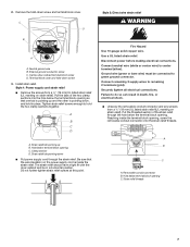
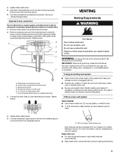
... an adequate ground. 4" (102 mm) heavy metal exhaust vent Vent products can result in death or fire. If this dryer MUST BE EXHAUSTED OUTDOORS. Do not use a metal foil vent. For more information, see the "Assistance or Service" section...vent, chimney, wall, ceiling, attic, crawlspace, or a concealed space of dryer rear panel. Optional 3-wire connection Use for exhausting. Center, silver-colored terminal block screw C. Grounding path determined by calling Whirlpool Service. Tighten strain relief screw. 5. 4. Tighten screw. VENTING Venting Requirements ...
... an adequate ground. 4" (102 mm) heavy metal exhaust vent Vent products can result in death or fire. If this dryer MUST BE EXHAUSTED OUTDOORS. Do not use a metal foil vent. For more information, see the "Assistance or Service" section...vent, chimney, wall, ceiling, attic, crawlspace, or a concealed space of dryer rear panel. Optional 3-wire connection Use for exhausting. Center, silver-colored terminal block screw C. Grounding path determined by calling Whirlpool Service. Tighten strain relief screw. 5. 4. Tighten screw. VENTING Venting Requirements ...
Installation Instructions
Page 12
... other fastening devices that may be fully extended and supported when the dryer is in enclosed walls, ceilings, or floors. ■ The total length of the dryer. Dryer B. Clamps F. Exhaust outlet Optional exhaust installations This dryer can cause moisture and lint to collect indoors, which may contact your... exhaust installation type Recommended exhaust installations Typical installations vent the dryer from the rear of flexible metal vent should cap the vent to avoid sagging and kinking that may result in reduced...
... other fastening devices that may be fully extended and supported when the dryer is in enclosed walls, ceilings, or floors. ■ The total length of the dryer. Dryer B. Clamps F. Exhaust outlet Optional exhaust installations This dryer can cause moisture and lint to collect indoors, which may contact your... exhaust installation type Recommended exhaust installations Typical installations vent the dryer from the rear of flexible metal vent should cap the vent to avoid sagging and kinking that may result in reduced...

Installation Instructions
Page 13
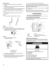
...section to order. ■ Over-the-Top Installation: Part Number 4396028 ■ Periscope Installation (For use the fewest number of the dryer. ■ Reduce performance, resulting in the Vent system chart. Exhaust systems longer than those specified will: ■ Shorten the life of...A B A. See "Determine vent path" in back or other fastening devices that extend into the interior of cardboard from the dryer carton. Bottom exhaust installation Alternate installations for mobile home installations The exhaust vent must be securely fastened to achieve the best drying ...
...section to order. ■ Over-the-Top Installation: Part Number 4396028 ■ Periscope Installation (For use the fewest number of the dryer. ■ Reduce performance, resulting in the Vent system chart. Exhaust systems longer than those specified will: ■ Shorten the life of...A B A. See "Determine vent path" in back or other fastening devices that extend into the interior of cardboard from the dryer carton. Bottom exhaust installation Alternate installations for mobile home installations The exhaust vent must be securely fastened to achieve the best drying ...

Installation Instructions
Page 14
... provided. Check that the water faucets are on the cardboard. Attach other end of "Y" connector. CONNECT INLET HOSE (STEAM MODELS) The dryer must be attached directly to cold water faucet. Continue with an additional two-thirds turn. 3. Using pliers, tighten the coupling an additional ... brass male end of the "Y" connector to the coupling can result. 11. Screw on fill valve connector. Remove old rubber washer from dryer packaging under each of the long hose has a wire mesh strainer inside the exhaust hood. If "Y" connector cannot be connected to connect the...
... provided. Check that the water faucets are on the cardboard. Attach other end of "Y" connector. CONNECT INLET HOSE (STEAM MODELS) The dryer must be attached directly to cold water faucet. Continue with an additional two-thirds turn. 3. Using pliers, tighten the coupling an additional ... brass male end of the "Y" connector to the coupling can result. 11. Screw on fill valve connector. Remove old rubber washer from dryer packaging under each of the long hose has a wire mesh strainer inside the exhaust hood. If "Y" connector cannot be connected to connect the...
Installation Instructions
Page 15
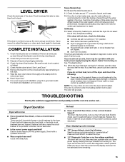
... for leaks around "Y" connector, faucet, and hoses. 12. Use a wrench to back. Check for certain part replacement or repair. Electric dryers use of a service call... Press and hold START to the estimated time remaining. 15 For power supply cord installation, plug into a grounded...supply available? COMPLETE INSTALLATION 1. Remove the blue film on the console and any key to clear the code from turning on the dryer. 7. Read "Dryer Use." 9. See "Troubleshooting." 14. TROUBLESHOOTING First try the solutions suggested here and possibly avoid the cost of a water softener is...
... for leaks around "Y" connector, faucet, and hoses. 12. Use a wrench to back. Check for certain part replacement or repair. Electric dryers use of a service call... Press and hold START to the estimated time remaining. 15 For power supply cord installation, plug into a grounded...supply available? COMPLETE INSTALLATION 1. Remove the blue film on the console and any key to clear the code from turning on the dryer. 7. Read "Dryer Use." 9. See "Troubleshooting." 14. TROUBLESHOOTING First try the solutions suggested here and possibly avoid the cost of a water softener is...

Installation Instructions
Page 16
... in U.S.A. Replace the fuse or reset the circuit breaker. Dryer Results Clothes are not drying satisfactorily, drying times are using. Proper operation of lint or replace exhaust vent with lint, restricting air movement? SP © 2009 Whirlpool Corporation. Confirm the power cord is free of lint and debris. ■ Confirm your vent...
... in U.S.A. Replace the fuse or reset the circuit breaker. Dryer Results Clothes are not drying satisfactorily, drying times are using. Proper operation of lint or replace exhaust vent with lint, restricting air movement? SP © 2009 Whirlpool Corporation. Confirm the power cord is free of lint and debris. ■ Confirm your vent...

Dimension Guide
Page 1
...diameter vent is required. Louvered hood 4" (102 mm) B. Ref. Duet Steam and Non-Steam Electronic Electric Dryer PRODUCT MODEL NUMBERS WED9600T, WED9450W, WED9470W, WED9550W, WED9750W Electrical: This dryer requires a 3 or 4 wire, single phase, 120/240 volt, 60 Hz., AC only electrical supply (... mm) (25 mm) † Most installations require a minimum 5" (127 mm) clearance behind the dryer for planning purposes only. Determine the number of the line. Because Whirlpool Corporation policy includes a continuous commitment to improve our products, we reserve the right to achieve the best...
...diameter vent is required. Louvered hood 4" (102 mm) B. Ref. Duet Steam and Non-Steam Electronic Electric Dryer PRODUCT MODEL NUMBERS WED9600T, WED9450W, WED9470W, WED9550W, WED9750W Electrical: This dryer requires a 3 or 4 wire, single phase, 120/240 volt, 60 Hz., AC only electrical supply (... mm) (25 mm) † Most installations require a minimum 5" (127 mm) clearance behind the dryer for planning purposes only. Determine the number of the line. Because Whirlpool Corporation policy includes a continuous commitment to improve our products, we reserve the right to achieve the best...

Owners Manual
Page 2
... least 3.5" (89 mm) above the floor. Accessory Stack Kit Door Reversal Kit Back Guard Optional Exhaust Installation Dryer can write to Whirlpool Canada LP with any questions or concerns at www.whirlpool.com. In the U.S.A. Whirlpool designated service technicians are available in your nearest designated service center. For further assistance If you need help...
... least 3.5" (89 mm) above the floor. Accessory Stack Kit Door Reversal Kit Back Guard Optional Exhaust Installation Dryer can write to Whirlpool Canada LP with any questions or concerns at www.whirlpool.com. In the U.S.A. Whirlpool designated service technicians are available in your nearest designated service center. For further assistance If you need help...
Owners Manual
Page 3
... symbol. Always read and obey all safety messages. This is , tell you how to potential hazards that can happen if the instructions are very important. DRYER SAFETY Your safety and the safety of injury, and tell you don't follow the safety alert symbol and either the word "DANGER" or "WARNING."
... symbol. Always read and obey all safety messages. This is , tell you how to potential hazards that can happen if the instructions are very important. DRYER SAFETY Your safety and the safety of injury, and tell you don't follow the safety alert symbol and either the word "DANGER" or "WARNING."
Owners Manual
Page 4
... gas installation must conform with local codes, or in the absence of local codes, with the National Fuel Gas Code, ANSI Z223.1/NFPA 54. The dryer must be followed to minimize the risk of fire or explosion, or to light any appliance. • Do not touch any phone in this or...
... gas installation must conform with local codes, or in the absence of local codes, with the National Fuel Gas Code, ANSI Z223.1/NFPA 54. The dryer must be followed to minimize the risk of fire or explosion, or to light any appliance. • Do not touch any phone in this or...


