Installation Instructions
Page 1
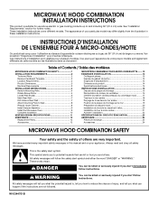
... above electric or gas cooking products up to Wall 8 Prepare Upper Cabinet 8 Install Damper Assembly 9 Install the Microwave Oven 9 Complete Installation 10 VENTING DESIGN SPECIFICATIONS 11 ASSISTANCE 12 Replacement Parts 12 Accessories 12 SÉCURITÉ DE... of others . Voir la section "Exigences d'installation" pour d'autres remarques. W10344701B Table of Contents / Table des matières MICROWAVE HOOD COMBINATION SAFETY 1 INSTALLATION REQUIREMENTS 2 Tools and Parts 2 Remove Cardboard Template 2 Location Requirements 2 Product Dimensions 3 Electrical Requirements ...
... above electric or gas cooking products up to Wall 8 Prepare Upper Cabinet 8 Install Damper Assembly 9 Install the Microwave Oven 9 Complete Installation 10 VENTING DESIGN SPECIFICATIONS 11 ASSISTANCE 12 Replacement Parts 12 Accessories 12 SÉCURITÉ DE... of others . Voir la section "Exigences d'installation" pour d'autres remarques. W10344701B Table of Contents / Table des matières MICROWAVE HOOD COMBINATION SAFETY 1 INSTALLATION REQUIREMENTS 2 Tools and Parts 2 Remove Cardboard Template 2 Location Requirements 2 Product Dimensions 3 Electrical Requirements ...
Installation Instructions
Page 2
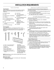
... using a rectangular to round transition piece, the 3" (7.6 cm) clearance needs to use as a rear wall template. 1. See "Rectangular to back of microwave oven) Cardboard template (part of installation. Power supply cord bushing (1) H. Location Requirements Check the opening . ■ Support for 1/4" x 2" lag screws...section. Read and follow the instructions provided with your builder or cabinet supplier to withstand the heat produced by the microwave oven for wood studs. Damper assembly (for use appropriate fasteners. The location must be combined. The piece inside...
... using a rectangular to round transition piece, the 3" (7.6 cm) clearance needs to use as a rear wall template. 1. See "Rectangular to back of microwave oven) Cardboard template (part of installation. Power supply cord bushing (1) H. Location Requirements Check the opening . ■ Support for 1/4" x 2" lag screws...section. Read and follow the instructions provided with your builder or cabinet supplier to withstand the heat produced by the microwave oven for wood studs. Damper assembly (for use appropriate fasteners. The location must be combined. The piece inside...
Installation Instructions
Page 3
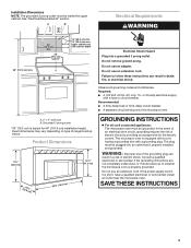
...of range/cooktop below. Recommended: ■ A time-delay fuse or time-delay circuit breaker. ■ A separate circuit serving only this microwave oven. The plug must be grounded. If the power supply cord is properly grounded. Installation Dimensions NOTE: The grounded 3 prong outlet must be... plugged into a grounded 3 prong outlet. Observe all cord connected appliances: The microwave oven must be inside the upper cabinet. Exact dimensions may vary depending on type of electric shock by providing an escape wire for 66...
...of range/cooktop below. Recommended: ■ A time-delay fuse or time-delay circuit breaker. ■ A separate circuit serving only this microwave oven. The plug must be grounded. If the power supply cord is properly grounded. Installation Dimensions NOTE: The grounded 3 prong outlet must be... plugged into a grounded 3 prong outlet. Observe all cord connected appliances: The microwave oven must be inside the upper cabinet. Exact dimensions may vary depending on type of electric shock by providing an escape wire for 66...
Installation Instructions
Page 4
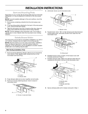
... sure damper plate tabs are using recirculation installation. Screws C. Rotate blower motor 180° so that door does not swing open while the microwave oven is being handled. A B A. Screws B. A A. Screws (in Step 3. 7. Slots 8. INSTALLATION INSTRUCTIONS Remove Mounting Plate Depending ... Blower motor 5. Exhaust port 6. Wall Venting Installation Only 1. Reattach blower motor to back of the microwave oven. Lift blower motor out of the microwave oven and lift up. Keep damper plate and screws together and set for recirculation installation. NOTE: Skip ...
... sure damper plate tabs are using recirculation installation. Screws C. Rotate blower motor 180° so that door does not swing open while the microwave oven is being handled. A B A. Screws B. A A. Screws (in Step 3. 7. Slots 8. INSTALLATION INSTRUCTIONS Remove Mounting Plate Depending ... Blower motor 5. Exhaust port 6. Wall Venting Installation Only 1. Reattach blower motor to back of the microwave oven. Lift blower motor out of the microwave oven and lift up. Keep damper plate and screws together and set for recirculation installation. NOTE: Skip ...
Installation Instructions
Page 5
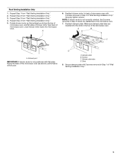
... Only." 2. Securely tighten screws. Repeat Step 1 from "Wall Venting Installation Only." 4. A 6. Make sure damper plate tabs are inserted into microwave oven. Roof Venting Installation Only 1. Exhaust port IMPORTANT: If blower motor is not correctly oriented, the 2 screws removed in the top of "...Wall Venting Installation Only." Reattach blower motor to the microwave oven. 7. Slots 8. Secure damper plate with 2 screws removed in Step 1 of microwave oven. NOTE: If blower motor is not positioned with flat sides facing the back of...
... Only." 2. Securely tighten screws. Repeat Step 1 from "Wall Venting Installation Only." 4. A 6. Make sure damper plate tabs are inserted into microwave oven. Roof Venting Installation Only 1. Exhaust port IMPORTANT: If blower motor is not correctly oriented, the 2 screws removed in the top of "...Wall Venting Installation Only." Reattach blower motor to the microwave oven. 7. Slots 8. Secure damper plate with 2 screws removed in Step 1 of microwave oven. NOTE: If blower motor is not positioned with flat sides facing the back of...
Installation Instructions
Page 6
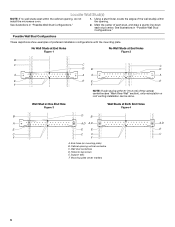
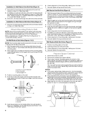
... lag screws E. Wall stud centerlines D. Possible Wall Stud Configurations These depictions show examples of the wall stud(s) within the cabinet opening, do not install the microwave oven. 1. Mark the center of the vertical centerline (see "Mark Rear Wall" section), only recirculation or roof venting installation can be done. Mounting plate center...
... lag screws E. Wall stud centerlines D. Possible Wall Stud Configurations These depictions show examples of the wall stud(s) within the cabinet opening, do not install the microwave oven. 1. Mark the center of the vertical centerline (see "Mark Rear Wall" section), only recirculation or roof venting installation can be done. Mounting plate center...
Installation Instructions
Page 7
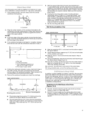
... nut; Installation for No Wall Studs at the hole(s) marked in "Locate Wall Stud(s)" section. Refer to the wall stud centerline(s). Mark Rear Wall The microwave oven must be 14¹⁄₈" (35.9 cm) from the centerline. 5. A A. Centerline 2. Top of "Mark Rear Wall." Holding the mounting plate in place, find...
... nut; Installation for No Wall Studs at the hole(s) marked in "Locate Wall Stud(s)" section. Refer to the wall stud centerline(s). Mark Rear Wall The microwave oven must be 14¹⁄₈" (35.9 cm) from the centerline. 5. A A. Centerline 2. Top of "Mark Rear Wall." Holding the mounting plate in place, find...
Installation Instructions
Page 8
... sure it is level. 7. Check alignment of the mounting plate facing forward, insert 1/4-20 x 3" round-head bolts through both ends. 1. Check alignment of the microwave oven. Insert lag screws into the upper cabinet align with the holes in the top of mounting plate, making sure it fits inside the frame... space for the toggle nut to go through the drywall, and finger tighten the bolt to use as guides. ■ If the wall behind the microwave oven (as at One End Hole" in the "Drill Holes in Step 2 of the mounting plate. Securely tighten the lag screw(s) and bolt. ...
... sure it is level. 7. Check alignment of the mounting plate facing forward, insert 1/4-20 x 3" round-head bolts through both ends. 1. Check alignment of the microwave oven. Insert lag screws into the upper cabinet align with the holes in the top of mounting plate, making sure it fits inside the frame... space for the toggle nut to go through the drywall, and finger tighten the bolt to use as guides. ■ If the wall behind the microwave oven (as at One End Hole" in the "Drill Holes in Step 2 of the mounting plate. Securely tighten the lag screw(s) and bolt. ...
Installation Instructions
Page 9
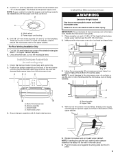
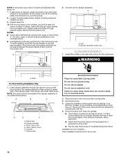
... vent in place. 9 B A A. These are for wall venting only) 1. Position the damper assembly on Upper Cabinet Template. 8. Handle the microwave oven gently. 1. Back of the shaded rectangular area "F" on the back of the upper cabinet. 5. Sheet metal screws 3. Secure damper assembly with... 2 sheet metal screws. For Roof Venting Installation Only 7. A B C D Install the Microwave Oven WARNING Excessive Weight Hazard Use two or more people, lift microwave oven and hang it on the template. NOTE: If venting through the power supply cord hole in back or...
... vent in place. 9 B A A. These are for wall venting only) 1. Position the damper assembly on Upper Cabinet Template. 8. Handle the microwave oven gently. 1. Back of the shaded rectangular area "F" on the back of the upper cabinet. 5. Sheet metal screws 3. Secure damper assembly with... 2 sheet metal screws. For Roof Venting Installation Only 7. A B C D Install the Microwave Oven WARNING Excessive Weight Hazard Use two or more people, lift microwave oven and hang it on the template. NOTE: If venting through the power supply cord hole in back or...
Installation Instructions
Page 10
...the damper plate. WARNING A. Bolts For Roof Venting Installation Only 1. A B C D E F A. Do not use an extension cord. With the microwave oven centered, and with sheet metal screw. The blocks must be added. Then secure with at most hardware stores. ■ Overtightening bolts may warp ... continues, call an electrician. ■ Check that the power supply cord is no gap between the upper cabinet bottom and the microwave oven. To avoid warping, wood filler blocks (installer to follow these instructions can result in place, insert bolts through the cabinet ...
...the damper plate. WARNING A. Bolts For Roof Venting Installation Only 1. A B C D E F A. Do not use an extension cord. With the microwave oven centered, and with sheet metal screw. The blocks must be added. Then secure with at most hardware stores. ■ Overtightening bolts may warp ... continues, call an electrician. ■ Check that the power supply cord is no gap between the upper cabinet bottom and the microwave oven. To avoid warping, wood filler blocks (installer to follow these instructions can result in place, insert bolts through the cabinet ...
Installation Instructions
Page 11
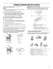
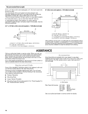
... = 3 m) 11 VENTING DESIGN SPECIFICATIONS This section is at least 3" (7.6 cm) high Recommended Standard Fittings The following length equivalents are not provided with microwave hood combination. ■ We do not recommend using a flexible metal vent. ■ To avoid possible product damage, be sure to vent air outside,... unless using the most direct route by minimizing the length of the vent and number of the microwave oven and the rectangular to round transition piece so that the damper can open fully. For optimal venting installation, we recommend: ...
... = 3 m) 11 VENTING DESIGN SPECIFICATIONS This section is at least 3" (7.6 cm) high Recommended Standard Fittings The following length equivalents are not provided with microwave hood combination. ■ We do not recommend using a flexible metal vent. ■ To avoid possible product damage, be sure to vent air outside,... unless using the most direct route by minimizing the length of the vent and number of the microwave oven and the rectangular to round transition piece so that the damper can open fully. For optimal venting installation, we recommend: ...
Installation Instructions
Page 12
... (2.4 m) 6" (15.2 cm) vent system = 73 ft (22.2 m) total A B 6 ft (1.8 m) 2 ft (0.6 m) C D A. When you call, you will need the microwave oven model number and serial number. Accessories Filler Panel Kits are available from sticking. Following is located behind the door. ■ Damper Assembly ■ Mounting...existing vent is 3" (7.6 cm) wide. To calculate the length of the system you need , add the equivalent lengths of the microwave oven. In addition, a rectangular 3" (7.6 cm) extension vent between the damper assembly and rectangular to round transition piece must not ...
... (2.4 m) 6" (15.2 cm) vent system = 73 ft (22.2 m) total A B 6 ft (1.8 m) 2 ft (0.6 m) C D A. When you call, you will need the microwave oven model number and serial number. Accessories Filler Panel Kits are available from sticking. Following is located behind the door. ■ Damper Assembly ■ Mounting...existing vent is 3" (7.6 cm) wide. To calculate the length of the system you need , add the equivalent lengths of the microwave oven. In addition, a rectangular 3" (7.6 cm) extension vent between the damper assembly and rectangular to round transition piece must not ...


