

Owner's Manual
Page 1
Owner's Manual Keep This Manual For Future Reference. EN
Owner's Manual Keep This Manual For Future Reference. EN

Owner's Manual
Page 2
...Contents 7 About the included discs 7 About the included DAW software .......... 7 About the utility software 7 Firmware updates 8 About this Owner's Manual 8 Conventions Used in this Manual 8 Control Surface & Rear Panel .......... 9 Control Surface 9 Rear Panel 16 Installing an Optional Card 18 Operating Basics 19 About the Display 19...I/O SLOT Spec 63 MIDI/USB/WORD CLOCK I/O Spec .... 64 Dimensions 64 Options 65 Rack Mounting the 01V96i Using RK1 Rack Mount Kit 65 Index 66 01V96i Block Diagram.......End of Manual 01V96i Level Diagram .......End of Manual 01V96i-Owner's Manual
...Contents 7 About the included discs 7 About the included DAW software .......... 7 About the utility software 7 Firmware updates 8 About this Owner's Manual 8 Conventions Used in this Manual 8 Control Surface & Rear Panel .......... 9 Control Surface 9 Rear Panel 16 Installing an Optional Card 18 Operating Basics 19 About the Display 19...I/O SLOT Spec 63 MIDI/USB/WORD CLOCK I/O Spec .... 64 Dimensions 64 Options 65 Rack Mounting the 01V96i Using RK1 Rack Mount Kit 65 Index 66 01V96i Block Diagram.......End of Manual 01V96i Level Diagram .......End of Manual 01V96i-Owner's Manual
Owner's Manual
Page 4
...van de levensduur of gelieve dan contact op te nemen met de vertegenwoordiging van Yamaha in uw land. • For the removal of the battery at the moment of the disposal at the end of this manual, meets FCC requirements. VAROITUS Paristo voi räjähtää, ...: EARTH BLUE : NEUTRAL BROWN : LIVE As the colours of the wires in the mains lead of Equipment : Digital Mixing Console Model Name : 01V96i This device complies with this product in harmful interference with the letter N or coloured BLACK. IMPORTANT: When connecting this product to accessories and/ or ...
...van de levensduur of gelieve dan contact op te nemen met de vertegenwoordiging van Yamaha in uw land. • For the removal of the battery at the moment of the disposal at the end of this manual, meets FCC requirements. VAROITUS Paristo voi räjähtää, ...: EARTH BLUE : NEUTRAL BROWN : LIVE As the colours of the wires in the mains lead of Equipment : Digital Mixing Console Model Name : 01V96i This device complies with this product in harmful interference with the letter N or coloured BLACK. IMPORTANT: When connecting this product to accessories and/ or ...

Owner's Manual
Page 5
...might spill into any dirt or dust which might accidentally fall over it. • Only use immediately and have the device inspected by qualified Yamaha service personnel. If it should be malfunctioning, discontinue use the voltage specified as candles, on its side or upside down. If you notice... always hold the bottom of the device when transporting or moving the device, remove all connected cables. • When setting up inside this manual in a safe place for example by leaving space between the devices and by the cord can result in any liquid such as vases, bottles...
...might spill into any dirt or dust which might accidentally fall over it. • Only use immediately and have the device inspected by qualified Yamaha service personnel. If it should be malfunctioning, discontinue use the voltage specified as candles, on its side or upside down. If you notice... always hold the bottom of the device when transporting or moving the device, remove all connected cables. • When setting up inside this manual in a safe place for example by leaving space between the devices and by the cord can result in any liquid such as vases, bottles...

Owner's Manual
Page 6
...point of extremely high temperature such as near another electrical product such as shown in this Owner's Manual are for all devices, set all devices. Then have qualified Yamaha service personnel replace the backup battery. When you wish to discard electrical and electronic equipment, please... contact your device. * The company names and product names in this Owner's Manual are the trademarks or registered trademarks of ...
...point of extremely high temperature such as near another electrical product such as shown in this Owner's Manual are for all devices, set all devices. Then have qualified Yamaha service personnel replace the backup battery. When you wish to discard electrical and electronic equipment, please... contact your device. * The company names and product names in this Owner's Manual are the trademarks or registered trademarks of ...

Owner's Manual
Page 7
... regarding the included software. Refer to the Steinberg website for choosing the Yamaha 01V96i Digital Mixing Console. Welcome Welcome 7 Welcome Thank you for any damages, either direct or consequential, that may result from the use of the included software and owner's manuals. • The included disc is software that allows you to make...
... regarding the included software. Refer to the Steinberg website for choosing the Yamaha 01V96i Digital Mixing Console. Welcome Welcome 7 Welcome Thank you for any damages, either direct or consequential, that may result from the use of the included software and owner's manuals. • The included disc is software that allows you to make...

Owner's Manual
Page 8
...clicking links are conveniences available only in which you can select pages. 01V96i-Owner's Manual The latest version of these possibilities. Using the PDF manual The reference manual is designed to allow the internal firmware to be updated in order ...to improve performance, add functionality, or fix problems. Firmware updates are performed with the product connected to physical buttons are not emphasized, for example, "press the [ENTER] button." References to a computer, so you must first install the "Yamaha...
...clicking links are conveniences available only in which you can select pages. 01V96i-Owner's Manual The latest version of these possibilities. Using the PDF manual The reference manual is designed to allow the internal firmware to be updated in order ...to improve performance, add functionality, or fix problems. Firmware updates are performed with the product connected to physical buttons are not emphasized, for example, "press the [ENTER] button." References to a computer, so you must first install the "Yamaha...

Owner's Manual
Page 9
Yamaha does not sell such a cover. If you fabricate and attach your own cover and attach it to the front panel to clear the control knobs and buttons. 01V96i-Owner's Manual Control Surface & Rear Panel Control Surface & Rear Panel 9 Control Surface & Rear Panel Control Surface AD Input Section (p. 10) SCENE ... USER DEFINED KEYS Section (p. 14) Note: Screw holes for attaching a cover are located at both sides of the AD input section of the 01V96i. (Size M3, horizontal spacing 417 mm, vertical spacing 36 mm.) You may wish to fabricate your own cover, make sure that the mounting ...
Yamaha does not sell such a cover. If you fabricate and attach your own cover and attach it to the front panel to clear the control knobs and buttons. 01V96i-Owner's Manual Control Surface & Rear Panel Control Surface & Rear Panel 9 Control Surface & Rear Panel Control Surface AD Input Section (p. 10) SCENE ... USER DEFINED KEYS Section (p. 14) Note: Screw holes for attaching a cover are located at both sides of the AD input section of the 01V96i. (Size M3, horizontal spacing 417 mm, vertical spacing 36 mm.) You may wish to fabricate your own cover, make sure that the mounting ...

Owner's Manual
Page 10
... panel turns on or off , and +4 dB to -40 dB when the Pad is on (pushed in), the 2TR IN signals (page 17) are selected. 01V96i-Owner's Manual Male XLR plug 1 (ground) 3 (cold) 2 (hot) 1/4" TRS phone plug Tip (hot) Ring (cold) Sleeve (ground) 2 INPUT connectors 13-16 These balanced TRS phone-type...
... panel turns on or off , and +4 dB to -40 dB when the Pad is on (pushed in), the 2TR IN signals (page 17) are selected. 01V96i-Owner's Manual Male XLR plug 1 (ground) 3 (cold) 2 (hot) 1/4" TRS phone plug Tip (hot) Ring (cold) Sleeve (ground) 2 INPUT connectors 13-16 These balanced TRS phone-type...

Owner's Manual
Page 11
... This 100mm motorized fader adjusts the final output level of the Stereo Out. 1 SEL 2 ON 0 5 10 15 20 30 40 50 60 70 3 STEREO 01V96i-Owner's Manual tion (8) is turned on the layer selected in the FADER MODE section (see page 13). When the button is turned off (raised), you can monitor...
... This 100mm motorized fader adjusts the final output level of the Stereo Out. 1 SEL 2 ON 0 5 10 15 20 30 40 50 60 70 3 STEREO 01V96i-Owner's Manual tion (8) is turned on the layer selected in the FADER MODE section (see page 13). When the button is turned off (raised), you can monitor...
Owner's Manual
Page 12
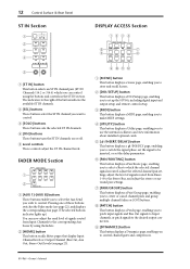
... one of these buttons switches the Fader mode (see page 22), and displays the corresponding Aux page. (The selected button's indicator lights up the 01V96i, including digital input and output setup and remote control setup. 3 [MIDI] button This button displays a MIDI page, enabling you to make MIDI ... of the button indicate the available ST IN channels. 2 [SEL] buttons These buttons select the ST IN channel you to control channel gates and compressors. 01V96i-Owner's Manual FADER MODE Section 1 2 FADER MODE AUX 1 AUX 2 AUX 3 AUX 4 AUX 5 AUX 6 AUX 7 AUX 8 HOME (METER) 1 [AUX 1]-[AUX 8] ...
... one of these buttons switches the Fader mode (see page 22), and displays the corresponding Aux page. (The selected button's indicator lights up the 01V96i, including digital input and output setup and remote control setup. 3 [MIDI] button This button displays a MIDI page, enabling you to make MIDI ... of the button indicate the available ST IN channels. 2 [SEL] buttons These buttons select the ST IN channel you to control channel gates and compressors. 01V96i-Owner's Manual FADER MODE Section 1 2 FADER MODE AUX 1 AUX 2 AUX 3 AUX 4 AUX 5 AUX 6 AUX 7 AUX 8 HOME (METER) 1 [AUX 1]-[AUX 8] ...

Owner's Manual
Page 13
... Channel layers.) 2 [MASTER] button This button selects the Master Layer as the layer controlled in cards. You can control Channels 1-16. Tab Scroll arrow 01V96i-Owner's Manual When the [17-32] button is turned on, you can use this layer to control external MIDI devices or computer-based DAWs. Selecting a tab at...
... Channel layers.) 2 [MASTER] button This button selects the Master Layer as the layer controlled in cards. You can control Channels 1-16. Tab Scroll arrow 01V96i-Owner's Manual When the [17-32] button is turned on, you can use this layer to control external MIDI devices or computer-based DAWs. Selecting a tab at...

Owner's Manual
Page 14
... current mix settings. (See page 42 for more information on Scene Memories.) 2 Scene Up [ ] / Down [ ] buttons These buttons select a Scene to these User Defined buttons. 01V96i-Owner's Manual pressing the Scene Down [ ] button decrements the selection.
... current mix settings. (See page 42 for more information on Scene Memories.) 2 Scene Up [ ] / Down [ ] buttons These buttons select a Scene to these User Defined buttons. 01V96i-Owner's Manual pressing the Scene Down [ ] button decrements the selection.

Owner's Manual
Page 15
... the [INC] button increments the value; pressing the [DEC] button decrements the value. Holding down a cursor button moves the cursor continuously in the corresponding direction. 01V96i-Owner's Manual Turning it counterclockwise decreases the value. Control Surface & Rear Panel Data Entry Section 3 1 DEC INC 4 Control Surface 15 SOLO Section 1 [SOLO] indicator This indicator...
... the [INC] button increments the value; pressing the [DEC] button decrements the value. Holding down a cursor button moves the cursor continuously in the corresponding direction. 01V96i-Owner's Manual Turning it counterclockwise decreases the value. Control Surface & Rear Panel Data Entry Section 3 1 DEC INC 4 Control Surface 15 SOLO Section 1 [SOLO] indicator This indicator...

Owner's Manual
Page 16
... connectors output monitoring signals or 2TR IN signals. The nominal signal level is turned off before you fail to a device that this switch is +4 dB. 01V96i-Owner's Manual Doing so will cause malfunctions. • Do not connect or disconnect a device while phantom power is supplied to four corresponding inputs. 16 Control Surface...
... connectors output monitoring signals or 2TR IN signals. The nominal signal level is turned off before you fail to a device that this switch is +4 dB. 01V96i-Owner's Manual Doing so will cause malfunctions. • Do not connect or disconnect a device while phantom power is supplied to four corresponding inputs. 16 Control Surface...

Owner's Manual
Page 17
...the Stereo Out signals. Close all applications. - Digital I/O Section 12 3 45 1 WORD CLOCK OUT connector This BNC connector outputs a wordclock signal from the 01V96i to a connected external device. 2 WORD CLOCK IN connector This BNC connector inputs a wordclock signal from a connected external device to a computer via the TO ... you power-on the console. • Before powering the console on/off and on, or between disconnecting and reconnecting the USB cable. 01V96i-Owner's Manual If you to the computer before you must do the following measures. The connector is +4 dB.
...the Stereo Out signals. Close all applications. - Digital I/O Section 12 3 45 1 WORD CLOCK OUT connector This BNC connector outputs a wordclock signal from the 01V96i to a connected external device. 2 WORD CLOCK IN connector This BNC connector inputs a wordclock signal from a connected external device to a computer via the TO ... you power-on the console. • Before powering the console on/off and on, or between disconnecting and reconnecting the USB cable. 01V96i-Owner's Manual If you to the computer before you must do the following measures. The connector is +4 dB.

Owner's Manual
Page 18
... the AC power cord from an I/O card can be patched to the Yamaha Pro Audio website. Caution Even when the POWER ON/OFF switch is turned off )-sound sources, multitrack and master recorders, 01V96i, monitoring power amplifiers. 2 AC IN connector This connector enables you are... desired bus or the direct signal of an input channel can be grounded correctly. 01V96i-Owner's Manual Input signals from the AC outlet. 3. 18 Control Surface & Rear Panel SLOT Section 1 1 SLOT Optional mini-YGDAI (Yamaha General Digital Audio Interface) I/O cards can install AD/DA cards or digital I/O ...
... the AC power cord from an I/O card can be patched to the Yamaha Pro Audio website. Caution Even when the POWER ON/OFF switch is turned off )-sound sources, multitrack and master recorders, 01V96i, monitoring power amplifiers. 2 AC IN connector This connector enables you are... desired bus or the direct signal of an input channel can be grounded correctly. 01V96i-Owner's Manual Input signals from the AC outlet. 3. 18 Control Surface & Rear Panel SLOT Section 1 1 SLOT Optional mini-YGDAI (Yamaha General Digital Audio Interface) I/O cards can install AD/DA cards or digital I/O ...

Owner's Manual
Page 19
... the current mix settings no longer match those of the currently-selected Scene memory. C Tab Scroll arrows These arrows indicate that was most-currently recalled. 01V96i-Owner's Manual If the selected Scene is receiving MIDI data via the MIDI IN port, USB port, or an installed card. 6 Surround mode indicator This indicator...
... the current mix settings no longer match those of the currently-selected Scene memory. C Tab Scroll arrows These arrows indicate that was most-currently recalled. 01V96i-Owner's Manual If the selected Scene is receiving MIDI data via the MIDI IN port, USB port, or an installed card. 6 Surround mode indicator This indicator...

Owner's Manual
Page 20
...To select a page for which a tab is displayed. To display the currently-hidden tabs, press the Right or Left [ ]/[ ] Tab Scroll button. Tip: The 01V96i remembers the current page and parameter when you move the cursor to a rotary control or fader you edit a value in Step 1. Parameter Boxes The parameter...group. The buttons also enable you to turn the function on the top panel to turn certain functions on where the page is cancelled. 01V96i-Owner's Manual Press the cursor buttons to confirm a change , and the flashing stops. You may need to press the [ENTER] button to move the ...
...To select a page for which a tab is displayed. To display the currently-hidden tabs, press the Right or Left [ ]/[ ] Tab Scroll button. Tip: The 01V96i remembers the current page and parameter when you move the cursor to a rotary control or fader you edit a value in Step 1. Parameter Boxes The parameter...group. The buttons also enable you to turn the function on the top panel to turn certain functions on where the page is cancelled. 01V96i-Owner's Manual Press the cursor buttons to confirm a change , and the flashing stops. You may need to press the [ENTER] button to move the ...

Owner's Manual
Page 21
...position and move the cursor within the title. Remote Layer Master Layer The currently-selected LAYER layer determines the function of the Layer settings. 01V96i-Owner's Manual LAYER buttons Layers Channel Strips 1-8 9-16 [1-16] button Input Channel Layer 1-16 Input Channels 1-16 [17-32] button Input Channel... • The STEREO [SEL] button, [ON] button, and [STE- Operating Basics Selecting Layers 21 Confirmation Messages For certain functions, the 01V96i prompts you for confirmation before executing the functions, as illustrated below. The cursor moves to cancel.
...position and move the cursor within the title. Remote Layer Master Layer The currently-selected LAYER layer determines the function of the Layer settings. 01V96i-Owner's Manual LAYER buttons Layers Channel Strips 1-8 9-16 [1-16] button Input Channel Layer 1-16 Input Channels 1-16 [17-32] button Input Channel... • The STEREO [SEL] button, [ON] button, and [STE- Operating Basics Selecting Layers 21 Confirmation Messages For certain functions, the 01V96i prompts you for confirmation before executing the functions, as illustrated below. The cursor moves to cancel.

