Owner's Manual
Page 4
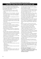
...waves from a test disc, bass sounds from the rear panel. If something drops into the YST port located on this unit in a safe place for any accident caused by this YAMAHA subwoofer system. YAMAHA shall not be held responsible for future reference. • Install this unit: Glass, china...; If you may get an electric shock. • Do not place this unit with the rear panel facing down on a TV. YAMAHA will radiate from electronic instruments, etc. falls by super-bass frequencies may be reached easily. • Secure placement or installation is dangerous ...
...waves from a test disc, bass sounds from the rear panel. If something drops into the YST port located on this unit in a safe place for any accident caused by this YAMAHA subwoofer system. YAMAHA shall not be held responsible for future reference. • Install this unit: Glass, china...; If you may get an electric shock. • Do not place this unit with the rear panel facing down on a TV. YAMAHA will radiate from electronic instruments, etc. falls by super-bass frequencies may be reached easily. • Secure placement or installation is dangerous ...

Owner's Manual
Page 5
...must be connected to the terminal which is marked with the letter N or coloured BLACK. ADJUSTING THE SUBWOOFER BEFORE USE 12 Frequency characteristics 13 ADVANCED YAMAHA ACTIVE SERVO TECHNOLOGY II 14 TROUBLESHOOTING 15 SPECIFICATIONS Backcover For Canadian Customers To prevent electric shock, match ...terminals of the amplifier 4 2 Connecting to speaker output terminals of the amplifier 6 Connecting to the INPUT1/ OUTPUT terminals of the subwoofer 8 Plug in the subwoofer to a TV set . • VOLTAGE SELECTOR (Asia and General models only) The voltage selector switch on the rear panel ...
...must be connected to the terminal which is marked with the letter N or coloured BLACK. ADJUSTING THE SUBWOOFER BEFORE USE 12 Frequency characteristics 13 ADVANCED YAMAHA ACTIVE SERVO TECHNOLOGY II 14 TROUBLESHOOTING 15 SPECIFICATIONS Backcover For Canadian Customers To prevent electric shock, match ...terminals of the amplifier 4 2 Connecting to speaker output terminals of the amplifier 6 Connecting to the INPUT1/ OUTPUT terminals of the subwoofer 8 Plug in the subwoofer to a TV set . • VOLTAGE SELECTOR (Asia and General models only) The voltage selector switch on the rear panel ...
Owner's Manual
Page 6
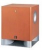
...-Bass (Quatre Dispersion Bass) technology is equipped with a linear port unique to Yamaha that the following parts are contained. FEATURES • This subwoofer system employs Advanced Yamaha Active Servo Technology II which Yamaha has developed for reproducing higher quality super-bass sound. (Refer to page 14... of the amplifier. • For the effective use of the subwoofer, the subwoofer's super-bass sound should be matched to the sounds of pressing the STANDBY/ON button to turn the power on Advanced Yamaha Active Servo Technology II.) This super-bass sound adds a more realistic...
...-Bass (Quatre Dispersion Bass) technology is equipped with a linear port unique to Yamaha that the following parts are contained. FEATURES • This subwoofer system employs Advanced Yamaha Active Servo Technology II which Yamaha has developed for reproducing higher quality super-bass sound. (Refer to page 14... of the amplifier. • For the effective use of the subwoofer, the subwoofer's super-bass sound should be matched to the sounds of pressing the STANDBY/ON button to turn the power on Advanced Yamaha Active Servo Technology II.) This super-bass sound adds a more realistic...

Owner's Manual
Page 7
...A B C Note There may die because the sound from happening, face the subwoofer system at the four corners on the bottom of the subwoofer to the wall. In such a case, face the subwoofer obliquely to prevent the subwoofer from the subwoofer when listening in fig. along the walls. B .) The placement shown in .... Use the non-skid pads Put the provided non-skid pads at an angle as in fig. A .) If using one subwoofer, the use of two subwoofers is placed directly facing the wall, the bass effect may be necessary to break up the parallel surfaces by vibrations etc. 3 ...
...A B C Note There may die because the sound from happening, face the subwoofer system at the four corners on the bottom of the subwoofer to the wall. In such a case, face the subwoofer obliquely to prevent the subwoofer from the subwoofer when listening in fig. along the walls. B .) The placement shown in .... Use the non-skid pads Put the provided non-skid pads at an angle as in fig. A .) If using one subwoofer, the use of two subwoofers is placed directly facing the wall, the bass effect may be necessary to break up the parallel surfaces by vibrations etc. 3 ...
Owner's Manual
Page 8
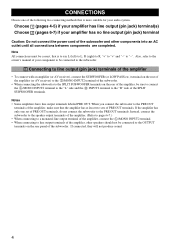
...L (left) to L, R (right) to R, "+" to "+" and "-" to "-". Also, refer to the owner's manual of your audio system. Instead, connect the subwoofer to the speaker output terminals of the amplifier. (Refer to pages 6-7.) • When connecting to a monaural line output terminal of the amplifier, connect the L /MONO... they will not produce sound. 4 CONNECTIONS Choose one set of PRE OUT terminals, do not connect the subwoofer to the PRE OUT terminals. When you connect the subwoofer to the PRE OUT terminals of the amplifier, make sure that is more suitable for your component to be...
...L (left) to L, R (right) to R, "+" to "+" and "-" to "-". Also, refer to the owner's manual of your audio system. Instead, connect the subwoofer to the speaker output terminals of the amplifier. (Refer to pages 6-7.) • When connecting to a monaural line output terminal of the amplifier, connect the L /MONO... they will not produce sound. 4 CONNECTIONS Choose one set of PRE OUT terminals, do not connect the subwoofer to the PRE OUT terminals. When you connect the subwoofer to the PRE OUT terminals of the amplifier, make sure that is more suitable for your component to be...

Owner's Manual
Page 9
■ Using one subwoofer Subwoofer OUTPUT TO SPEAKERS INPUT 1 FROM AMPLIFIER INPUT PHASE 2 L /MONO NORM REV R AUTO STANDBY HIGH LOW OFF VOLTAGE SELECTOR 220V-240V 110V-120V POWER ON OFF ... 1 FROM AMPLIFIER CONNECTIONS Mono pin cable (not included) Audio pin cable (not included) ■ Using two subwoofers OUTPUT TO SPEAKERS INPUT 2 L /MONO Mono pin cable(not included) OUTPUT TO SPEAKERS INPUT 2 L /MONO Subwoofer INPUT 1 FROM AMPLIFIER R Subwoofer OUTPUT TO SPEAKERS INPUT 1 FROM AMPLIFIER INPUT PHASE 2 L /MONO NORM REV R AUTO STANDBY HIGH LOW OFF...
■ Using one subwoofer Subwoofer OUTPUT TO SPEAKERS INPUT 1 FROM AMPLIFIER INPUT PHASE 2 L /MONO NORM REV R AUTO STANDBY HIGH LOW OFF VOLTAGE SELECTOR 220V-240V 110V-120V POWER ON OFF ... 1 FROM AMPLIFIER CONNECTIONS Mono pin cable (not included) Audio pin cable (not included) ■ Using two subwoofers OUTPUT TO SPEAKERS INPUT 2 L /MONO Mono pin cable(not included) OUTPUT TO SPEAKERS INPUT 2 L /MONO Subwoofer INPUT 1 FROM AMPLIFIER R Subwoofer OUTPUT TO SPEAKERS INPUT 1 FROM AMPLIFIER INPUT PHASE 2 L /MONO NORM REV R AUTO STANDBY HIGH LOW OFF...

Owner's Manual
Page 10
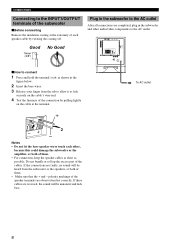
... output terminals, see page 7. ■ Using one set of front speaker output terminals of the amplifier to the INPUT1 terminals of the subwoofer, and connect the other set of the amplifier Select this method if your amplifier has two sets of front speaker output terminals and both... ON OFF To AC outlet OUTPUT TO SPEAKERS INPUT 2 L /MONO R INPUT 1 FROM AMPLIFIER OUTPUT TO SPEAKERS INPUT 1 FROM AMPLIFIER INPUT 2 L /MONO R Subwoofer OUTPUT TO SPEAKERS INPUT 1 FROM AMPLIFIER INPUT PHASE 2 L /MONO NORM REV R AUTO STANDBY HIGH LOW OFF VOLTAGE SELECTOR 220V-240V 110V-120V POWER ON OFF...
... output terminals, see page 7. ■ Using one set of front speaker output terminals of the amplifier to the INPUT1 terminals of the subwoofer, and connect the other set of the amplifier Select this method if your amplifier has two sets of front speaker output terminals and both... ON OFF To AC outlet OUTPUT TO SPEAKERS INPUT 2 L /MONO R INPUT 1 FROM AMPLIFIER OUTPUT TO SPEAKERS INPUT 1 FROM AMPLIFIER INPUT 2 L /MONO R Subwoofer OUTPUT TO SPEAKERS INPUT 1 FROM AMPLIFIER INPUT PHASE 2 L /MONO NORM REV R AUTO STANDBY HIGH LOW OFF VOLTAGE SELECTOR 220V-240V 110V-120V POWER ON OFF...

Owner's Manual
Page 11
...INPUT 2 L /MONO R INPUT 1 FROM AMPLIFIER Amplifier To AC outlet Speaker output terminals ■ Using two subwoofers (with speaker cables) Right front speaker Left front speaker Subwoofer OUTPUT TO SPEAKERS INPUT 1 FROM AMPLIFIER INPUT PHASE 2 L /MONO NORM REV R AUTO STANDBY HIGH LOW OFF...L /MONO R INPUT 1 FROM AMPLIFIER To AC outlet Speaker output terminals OUTPUT TO SPEAKERS INPUT 2 L /MONO R INPUT 1 FROM AMPLIFIER Amplifier Subwoofer OUTPUT TO SPEAKERS INPUT 1 FROM AMPLIFIER INPUT PHASE 2 L /MONO NORM REV R AUTO STANDBY HIGH LOW OFF VOLTAGE SELECTOR 220V-240V 110V-120V ...
...INPUT 2 L /MONO R INPUT 1 FROM AMPLIFIER Amplifier To AC outlet Speaker output terminals ■ Using two subwoofers (with speaker cables) Right front speaker Left front speaker Subwoofer OUTPUT TO SPEAKERS INPUT 1 FROM AMPLIFIER INPUT PHASE 2 L /MONO NORM REV R AUTO STANDBY HIGH LOW OFF...L /MONO R INPUT 1 FROM AMPLIFIER To AC outlet Speaker output terminals OUTPUT TO SPEAKERS INPUT 2 L /MONO R INPUT 1 FROM AMPLIFIER Amplifier Subwoofer OUTPUT TO SPEAKERS INPUT 1 FROM AMPLIFIER INPUT PHASE 2 L /MONO NORM REV R AUTO STANDBY HIGH LOW OFF VOLTAGE SELECTOR 220V-240V 110V-120V ...
Owner's Manual
Page 12
... the speakers, or both of them . • For connection, keep the speaker cables as short as shown in the subwoofer and other , because this could damage the subwoofer or the amplifier, or both of them . • Make sure that the + and - OUTPUT TO SPEAKERS INPUT 1 FROM AMPLIFIER INPUT ...other audio/video components to the AC outlet. If the connections are observed and set correctly. CONNECTIONS Connecting to the INPUT1/OUTPUT terminals of the subwoofer ■ Before connecting Remove the insulation coating at the terminal. + To AC outlet 1 2 - Notes • Do not let the bare...
... the speakers, or both of them . • For connection, keep the speaker cables as short as shown in the subwoofer and other , because this could damage the subwoofer or the amplifier, or both of them . • Make sure that the + and - OUTPUT TO SPEAKERS INPUT 1 FROM AMPLIFIER INPUT ...other audio/video components to the AC outlet. If the connections are observed and set correctly. CONNECTIONS Connecting to the INPUT1/OUTPUT terminals of the subwoofer ■ Before connecting Remove the insulation coating at the terminal. + To AC outlet 1 2 - Notes • Do not let the bare...

Owner's Manual
Page 13
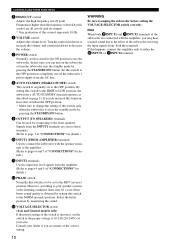
... R AB 1 POWER INDICATOR Lights up in green.) Press again to set in the ON position. (The power indicator lights up in green while the subwoofer is well reproduced. 4 HIGH CUT FILTER button ON: Enables the HIGH CUT control setting (5). By pressing the button again so that it pops out at... MOVIE position, the bass sound in video software is on the power when the POWER switch is set the subwoofer in the standby mode. (The power indicator goes off.) Standby mode The subwoofer is still using a small amount of power in this mode. 3 B.A.S.S. (Bass Action Selector System) button When this ...
... R AB 1 POWER INDICATOR Lights up in green.) Press again to set in the ON position. (The power indicator lights up in green while the subwoofer is well reproduced. 4 HIGH CUT FILTER button ON: Enables the HIGH CUT control setting (5). By pressing the button again so that it pops out at... MOVIE position, the bass sound in video software is on the power when the POWER switch is set the subwoofer in the standby mode. (The power indicator goes off.) Standby mode The subwoofer is still using a small amount of power in this mode. 3 B.A.S.S. (Bass Action Selector System) button When this ...
Owner's Manual
Page 14
...are sent to these terminals. (Refer to page 7 of "CONNECTIONS" for details.) 0 INPUT1 (FROM AMPLIFIER) terminals Used to connect the subwoofer with the amplifier, you can turn on page 11. Note When both the terminals. Frequencies higher than the frequency selected by pressing the STANDBY... the listening condition, there may hear a mixed sound due to the effect of this happens, connect the amplifier only to unplug the subwoofer before setting the VOLTAGE SELECTOR switch correctly. If this control represents 10 Hz. 6 VOLUME control Adjusts the volume level. CONTROLS AND THEIR...
...are sent to these terminals. (Refer to page 7 of "CONNECTIONS" for details.) 0 INPUT1 (FROM AMPLIFIER) terminals Used to connect the subwoofer with the amplifier, you can turn on page 11. Note When both the terminals. Frequencies higher than the frequency selected by pressing the STANDBY... the listening condition, there may hear a mixed sound due to the effect of this happens, connect the amplifier only to unplug the subwoofer before setting the VOLTAGE SELECTOR switch correctly. If this control represents 10 Hz. 6 VOLUME control Adjusts the volume level. CONTROLS AND THEIR...
Owner's Manual
Page 15
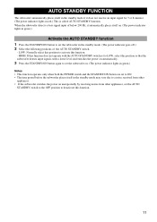
...an input signal for 7 or 8 minutes. (The power indicator lights in red.) This is called AUTO STANDBY function. AUTO STANDBY FUNCTION The subwoofer automatically places itself in the standby mode if it automatically places itself in the standby mode may vary due to a noise received from other appliances.... • If the subwoofer switches the power on . (The power indicator lights in green.) Activate the AUTO STANDBY function 1 Press the STANDBY/ON button to set the...
...an input signal for 7 or 8 minutes. (The power indicator lights in red.) This is called AUTO STANDBY function. AUTO STANDBY FUNCTION The subwoofer automatically places itself in the standby mode if it automatically places itself in the standby mode may vary due to a noise received from other appliances.... • If the subwoofer switches the power on . (The power indicator lights in green.) Activate the AUTO STANDBY function 1 Press the STANDBY/ON button to set the...
Owner's Manual
Page 16
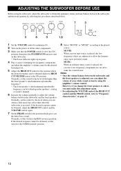
...Set the PHASE switch to the REV (reverse) position. Normally, set to the ON position, then press the STANDBY/ON button to turn on the subwoofer. * The Power indicator lights up in green. 4 Play a source containing low-frequency components and adjust the amplifier's volume control to the desired ...can be looked up in the speakers' catalog or owner's manual. 6 Increase the volume gradually to adjust the volume balance between the subwoofer and the front speakers. If the desired response cannot be obtained and press HIGH CUT FILTER button to "Frequency characteristics" on the power...
...Set the PHASE switch to the REV (reverse) position. Normally, set to the ON position, then press the STANDBY/ON button to turn on the subwoofer. * The Power indicator lights up in green. 4 Play a source containing low-frequency components and adjust the amplifier's volume control to the desired ...can be looked up in the speakers' catalog or owner's manual. 6 Increase the volume gradually to adjust the volume balance between the subwoofer and the front speakers. If the desired response cannot be obtained and press HIGH CUT FILTER button to "Frequency characteristics" on the power...
Owner's Manual
Page 17
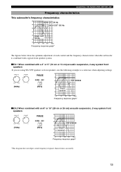
dB PHASE 90 NORM REV 80 YST-SW325 (90Hz) (REV) 70 60 Front speaker 50 40 20 50 100 200 500Hz Frequency response ...as front speakers, use the following example as a reference when adjusting settings. ADJUSTING THE SUBWOOFER BEFORE USE Frequency characteristics This subwoofer's frequency characteristics dB HIGH CUT 90 Hz 90 HIGH CUT 150 Hz 80 70 60 HIGH... subwoofer is combined with a typical front speaker system. ■ EX.1 When combined with an 8" or 10" (20 cm or 25 cm) acoustic suspension, 2 way system front speakers (70Hz) PHASE NORM REV (REV) dB 90 80 YST-SW325 ...
dB PHASE 90 NORM REV 80 YST-SW325 (90Hz) (REV) 70 60 Front speaker 50 40 20 50 100 200 500Hz Frequency response ...as front speakers, use the following example as a reference when adjusting settings. ADJUSTING THE SUBWOOFER BEFORE USE Frequency characteristics This subwoofer's frequency characteristics dB HIGH CUT 90 Hz 90 HIGH CUT 150 Hz 80 70 60 HIGH... subwoofer is combined with a typical front speaker system. ■ EX.1 When combined with an 8" or 10" (20 cm or 25 cm) acoustic suspension, 2 way system front speakers (70Hz) PHASE NORM REV (REV) dB 90 80 YST-SW325 ...
Owner's Manual
Page 19
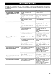
... parallel surface by standing waves. Play a source sound with few bass frequencies is L (left) to L, R (right) to R, "+" to "+" and "-" to "-". Reposition the subwoofer or break up . Set the AUTO STANDBY switch to the "HIGH" or "LOW" position. Sound level is too low. The level of the PHASE switch... switch to the ON position. TROUBLESHOOTING Refer to the chart below do not help, disconnect the power cord and contact your authorized YAMAHA dealer or service center. Problem Power is not supplied even though the STANDBY/ON button is set to the OFF position. No sound. ...
... parallel surface by standing waves. Play a source sound with few bass frequencies is L (left) to L, R (right) to R, "+" to "+" and "-" to "-". Reposition the subwoofer or break up . Set the AUTO STANDBY switch to the "HIGH" or "LOW" position. Sound level is too low. The level of the PHASE switch... switch to the ON position. TROUBLESHOOTING Refer to the chart below do not help, disconnect the power cord and contact your authorized YAMAHA dealer or service center. Problem Power is not supplied even though the STANDBY/ON button is set to the OFF position. No sound. ...


