
User Guide
Page 3
... to use the web configurator to configure the Switch. • Support Disc Refer to configure the Switch. The Technical Writing Team, ZyXEL Communications Corp., 6 Innovation Road II, Science-Based Industrial Park, Hsinchu, 30099, Taiwan. It contains information on setting up and running right away. MGS-3712/MGS-3712F User's Guide 3 Note: It is designed to configure...
... to use the web configurator to configure the Switch. • Support Disc Refer to configure the Switch. The Technical Writing Team, ZyXEL Communications Corp., 6 Innovation Road II, Science-Based Industrial Park, Hsinchu, 30099, Taiwan. It contains information on setting up and running right away. MGS-3712/MGS-3712F User's Guide 3 Note: It is designed to configure...
User Guide
Page 5
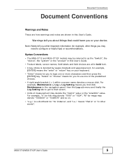
...things you or your keyboard. • "Enter" means for you first click Maintenance in other words". Syntax Conventions • The MGS-3712 and MGS-3712F models may be referred to as the "Switch", the "device", the "system" or the "product" in this User's Guide. • Product labels, screen names, field...is denoted by square brackets and uppercase text, for example, [ENTER] means the "enter" or "return" key on your device. MGS-3712/MGS-3712F User's Guide 5 Document Conventions Document Conventions Warnings and Notes These are how warnings and notes are all in this User's Guide.
...things you or your keyboard. • "Enter" means for you first click Maintenance in other words". Syntax Conventions • The MGS-3712 and MGS-3712F models may be referred to as the "Switch", the "device", the "system" or the "product" in this User's Guide. • Product labels, screen names, field...is denoted by square brackets and uppercase text, for example, [ENTER] means the "enter" or "return" key on your device. MGS-3712/MGS-3712F User's Guide 5 Document Conventions Document Conventions Warnings and Notes These are how warnings and notes are all in this User's Guide.
User Guide
Page 6
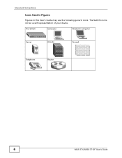
The Switch icon is not an exact representation of your device. The Switch Computer Notebook computer Server DSLAM Firewall Telephone Router 6 MGS-3712/MGS-3712F User's Guide Document Conventions Icons Used in Figures Figures in this User's Guide may use the following generic icons.
The Switch icon is not an exact representation of your device. The Switch Computer Notebook computer Server DSLAM Firewall Telephone Router 6 MGS-3712/MGS-3712F User's Guide Document Conventions Icons Used in Figures Figures in this User's Guide may use the following generic icons.
User Guide
Page 9
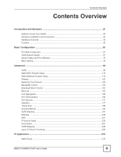
Contents Overview Contents Overview Introduction and Hardware 21 Getting to Know Your Switch ...23 Hardware Installation and Connection 29 Hardware Overview ...33 Tutorials ...45 Basic Configuration ...55 The Web Configurator ...57 Initial Setup Example ...67 System Status and ... ...197 Multicast ...205 AAA ...221 IP Source Guard ...235 Loop Guard ...261 VLAN Mapping ...265 Layer 2 Protocol Tunneling ...269 IP Application ...273 Static Route ...275 MGS-3712/MGS-3712F User's Guide 9
Contents Overview Contents Overview Introduction and Hardware 21 Getting to Know Your Switch ...23 Hardware Installation and Connection 29 Hardware Overview ...33 Tutorials ...45 Basic Configuration ...55 The Web Configurator ...57 Initial Setup Example ...67 System Status and ... ...197 Multicast ...205 AAA ...221 IP Source Guard ...235 Loop Guard ...261 VLAN Mapping ...265 Layer 2 Protocol Tunneling ...269 IP Application ...273 Static Route ...275 MGS-3712/MGS-3712F User's Guide 9
User Guide
Page 11
... Installation Procedure 29 2.3 Mounting the Switch on a Rack 30 2.3.1 Rack-mounted Installation Requirements 30 2.3.2 Attaching the Mounting Brackets to the Switch 31 2.3.3 Mounting the Switch on a Rack 32 Chapter 3 Hardware Overview...33 3.1 Front Panel ...33 3.1.1 Console Port ...35 3.1.2 Gigabit Ethernet Ports 35 3.1.3 Mini-GBIC Slots ...36 3.1.4 Management Port ...38 MGS-3712/MGS-3712F User's Guide 11
... Installation Procedure 29 2.3 Mounting the Switch on a Rack 30 2.3.1 Rack-mounted Installation Requirements 30 2.3.2 Attaching the Mounting Brackets to the Switch 31 2.3.3 Mounting the Switch on a Rack 32 Chapter 3 Hardware Overview...33 3.1 Front Panel ...33 3.1.1 Console Port ...35 3.1.2 Gigabit Ethernet Ports 35 3.1.3 Mini-GBIC Slots ...36 3.1.4 Management Port ...38 MGS-3712/MGS-3712F User's Guide 11

User Guide
Page 12
... Screen ...58 5.3.1 Change Your Password 62 5.4 Saving Your Configuration 62 5.5 Switch Lockout ...62 5.6 Resetting the Switch ...63 5.6.1 Reload the Configuration File 63 5.7 Logging Out of the Web ...Configurator 64 5.8 Help ...65 Chapter 6 Initial Setup Example...67 6.1 Overview ...67 6.1.1 Creating a VLAN ...67 6.1.2 Setting Port VID ...68 6.2 Configuring Switch Management IP Address 70 Chapter 7 System Status and Port Statistics 73 7.1 Overview ...73 7.2 Port Status Summary ...73 12 MGS-3712/MGS-3712F...
... Screen ...58 5.3.1 Change Your Password 62 5.4 Saving Your Configuration 62 5.5 Switch Lockout ...62 5.6 Resetting the Switch ...63 5.6.1 Reload the Configuration File 63 5.7 Logging Out of the Web ...Configurator 64 5.8 Help ...65 Chapter 6 Initial Setup Example...67 6.1 Overview ...67 6.1.1 Creating a VLAN ...67 6.1.2 Setting Port VID ...68 6.2 Configuring Switch Management IP Address 70 Chapter 7 System Status and Port Statistics 73 7.1 Overview ...73 7.2 Port Status Summary ...73 12 MGS-3712/MGS-3712F...
User Guide
Page 13
Table of Contents 7.2.1 Status: Port Details 75 Chapter 8 Basic Setting ...79 8.1 Overview ...79 8.2 System Information ...80 8.3 General Setup ...82 8.4 Introduction to VLANs ...84 8.5 Switch Setup Screen ...85 8.6 IP Setup ...87 8.6.1 Management IP Addresses 87 8.7 Port Setup ...91 Part III: Advanced 93 Chapter 9 VLAN ...95 9.1 Introduction to IEEE 802.1Q ... VLAN Setup 111 9.11.1 Configure a Port-based VLAN 112 Chapter 10 Static MAC Forward Setup 115 10.1 Overview ...115 10.2 Configuring Static MAC Forwarding 115 MGS-3712/MGS-3712F User's Guide 13
Table of Contents 7.2.1 Status: Port Details 75 Chapter 8 Basic Setting ...79 8.1 Overview ...79 8.2 System Information ...80 8.3 General Setup ...82 8.4 Introduction to VLANs ...84 8.5 Switch Setup Screen ...85 8.6 IP Setup ...87 8.6.1 Management IP Addresses 87 8.7 Port Setup ...91 Part III: Advanced 93 Chapter 9 VLAN ...95 9.1 Introduction to IEEE 802.1Q ... VLAN Setup 111 9.11.1 Configure a Port-based VLAN 112 Chapter 10 Static MAC Forward Setup 115 10.1 Overview ...115 10.2 Configuring Static MAC Forwarding 115 MGS-3712/MGS-3712F User's Guide 13

User Guide
Page 19
....3.5 Configuring SNMP Trap Group 318 34.3.6 Setting Up Login Accounts 319 34.4 SSH Overview ...320 34.5 How SSH works ...321 34.6 SSH Implementation on the Switch 322 34.6.1 Requirements for Using SSH 322 34.7 Introduction to HTTPS ...322 34.8 HTTPS Example ...323 34.8.1 Internet Explorer Warning Messages 323 34.8.2 Netscape Navigator... ...331 36.1 Syslog Overview ...331 36.2 Syslog Setup ...332 36.3 Syslog Server Setup ...333 Chapter 37 Cluster Management...335 37.1 Cluster Management Status Overview 335 MGS-3712/MGS-3712F User's Guide 19
....3.5 Configuring SNMP Trap Group 318 34.3.6 Setting Up Login Accounts 319 34.4 SSH Overview ...320 34.5 How SSH works ...321 34.6 SSH Implementation on the Switch 322 34.6.1 Requirements for Using SSH 322 34.7 Introduction to HTTPS ...322 34.8 HTTPS Example ...323 34.8.1 Internet Explorer Warning Messages 323 34.8.2 Netscape Navigator... ...331 36.1 Syslog Overview ...331 36.2 Syslog Setup ...332 36.3 Syslog Server Setup ...333 Chapter 37 Cluster Management...335 37.1 Cluster Management Status Overview 335 MGS-3712/MGS-3712F User's Guide 19

User Guide
Page 20
Table of Contents 37.2 Cluster Management Status 336 37.2.1 Cluster Member Switch Management 337 37.3 Clustering Management Configuration 340 Chapter 38 MAC Table...343 38.1 MAC Table Overview ...343 38.2 Viewing the MAC Table... & Product Specifications 351 Chapter 41 Troubleshooting...353 41.1 Power, Hardware Connections, and LEDs 353 41.2 Switch Access and Login 354 41.3 Switch Configuration ...356 Chapter 42 Product Specifications ...357 Part VII: Appendices and Index 365 Appendix A Common Services 367 Appendix B Legal Information 371 Index...375 20 MGS-3712/MGS-3712F User's Guide
Table of Contents 37.2 Cluster Management Status 336 37.2.1 Cluster Member Switch Management 337 37.3 Clustering Management Configuration 340 Chapter 38 MAC Table...343 38.1 MAC Table Overview ...343 38.2 Viewing the MAC Table... & Product Specifications 351 Chapter 41 Troubleshooting...353 41.1 Power, Hardware Connections, and LEDs 353 41.2 Switch Access and Login 354 41.3 Switch Configuration ...356 Chapter 42 Product Specifications ...357 Part VII: Appendices and Index 365 Appendix A Common Services 367 Appendix B Legal Information 371 Index...375 20 MGS-3712/MGS-3712F User's Guide

User Guide
Page 21
PART I Introduction and Hardware Getting to Know Your Switch (23) Hardware Installation and Connection (29) Hardware Overview (33) Tutorials (45) 21
PART I Introduction and Hardware Getting to Know Your Switch (23) Hardware Installation and Connection (29) Hardware Overview (33) Tutorials (45) 21
User Guide
Page 23
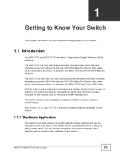
... in the near future. CHAPTER 1 Getting to the Switch. This section shows a few examples of the Switch. 1.1 Introduction The MGS-3712 and MGS-3712F are layer 2 stand-alone Gigabit Ethernet (GbE) switches. The Switch can connect computers and servers directly to the Switch's port or connect other switches to Know Your Switch This chapter introduces the main features and applications...
... in the near future. CHAPTER 1 Getting to the Switch. This section shows a few examples of the Switch. 1.1 Introduction The MGS-3712 and MGS-3712F are layer 2 stand-alone Gigabit Ethernet (GbE) switches. The Switch can connect computers and servers directly to the Switch's port or connect other switches to Know Your Switch This chapter introduces the main features and applications...
User Guide
Page 24
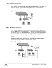
...mini-GBIC port on the server. To expand the network, simply add more networking devices such as switches, routers, computers, print servers etc. You can alleviate bandwidth contention and eliminate server and network ...Switch. Figure 1 Backbone Application 1.1.2 Bridging Example In this example application the Switch connects different company departments (RD and Sales) to Know Your Switch In this example, all computers can connect to centralize multiple servers at a single location. Chapter 1 Getting to the corporate backbone. Figure 2 Bridging Application 24 MGS-3712/MGS-3712F...
...mini-GBIC port on the server. To expand the network, simply add more networking devices such as switches, routers, computers, print servers etc. You can alleviate bandwidth contention and eliminate server and network ...Switch. Figure 1 Backbone Application 1.1.2 Bridging Example In this example application the Switch connects different company departments (RD and Sales) to Know Your Switch In this example, all computers can connect to centralize multiple servers at a single location. Chapter 1 Getting to the corporate backbone. Figure 2 Bridging Application 24 MGS-3712/MGS-3712F...
User Guide
Page 25
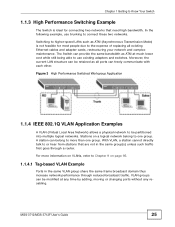
...existing Ethernet cables and adapter cards, restructuring your network and complex maintenance. Chapter 1 Getting to Know Your Switch 1.1.3 High Performance Switching Example The Switch is not feasible for connecting two networks that are not in the same VLAN group share the same frame...Performance Switched Workgroup Application 1.1.4 IEEE 802.1Q VLAN Application Examples A VLAN (Virtual Local Area Network) allows a physical network to be modified at much lower cost while still being able to use trunking to or hear from stations that need high bandwidth. MGS-3712/MGS-3712F User...
...existing Ethernet cables and adapter cards, restructuring your network and complex maintenance. Chapter 1 Getting to Know Your Switch 1.1.3 High Performance Switching Example The Switch is not feasible for connecting two networks that are not in the same VLAN group share the same frame...Performance Switched Workgroup Application 1.1.4 IEEE 802.1Q VLAN Application Examples A VLAN (Virtual Local Area Network) allows a physical network to be modified at much lower cost while still being able to use trunking to or hear from stations that need high bandwidth. MGS-3712/MGS-3712F User...

User Guide
Page 26
... the web configurator and in the same VLAN as numbers and letters. 26 MGS-3712/MGS-3712F User's Guide See Chapter 5 on page 306. • Cluster Management. Use FTP for everyday management of the following things regularly to make the Switch more secure and to other VLAN groups too. Use a password that consists of...
... the web configurator and in the same VLAN as numbers and letters. 26 MGS-3712/MGS-3712F User's Guide See Chapter 5 on page 306. • Cluster Management. Use FTP for everyday management of the following things regularly to make the Switch more secure and to other VLAN groups too. Use a password that consists of...

User Guide
Page 27
If you forget your last configuration. You could simply restore your password, you would not have to reset the Switch to its factory default settings. Restoring an earlier working configuration may be useful if the device becomes unstable or even crashes. MGS-3712/MGS-3712F User's Guide 27 If you backed up the configuration (and make sure you know how to restore it in a safe place. • Back up an earlier configuration file, you will have to totally re-configure the Switch. Chapter 1 Getting to Know Your Switch • Write down the password and put it ).
If you forget your last configuration. You could simply restore your password, you would not have to reset the Switch to its factory default settings. Restoring an earlier working configuration may be useful if the device becomes unstable or even crashes. MGS-3712/MGS-3712F User's Guide 27 If you backed up the configuration (and make sure you know how to restore it in a safe place. • Back up an earlier configuration file, you will have to totally re-configure the Switch. Chapter 1 Getting to Know Your Switch • Write down the password and put it ).

User Guide
Page 28
Chapter 1 Getting to Know Your Switch 28 MGS-3712/MGS-3712F User's Guide
Chapter 1 Getting to Know Your Switch 28 MGS-3712/MGS-3712F User's Guide

User Guide
Page 29
...you how to allow at least 4 inches (10 cm) of clearance at the front and 3.4 inches (8 cm) at the back of the Switch and the connected cables. Note: For proper ventilation, allow air circulation and the attachment of cables and the power cord. 4 Remove the adhesive ...the Switch. 2.1 Installation Scenarios The Switch can be placed on a desktop or rack-mounted on a smooth, level surface strong enough to support the weight of the Switch. Make sure there is a power outlet nearby. 3 Make sure there is clean and dry. 2 Set the Switch on a standard EIA rack. MGS-3712/MGS-3712F User's...
...you how to allow at least 4 inches (10 cm) of clearance at the front and 3.4 inches (8 cm) at the back of the Switch and the connected cables. Note: For proper ventilation, allow air circulation and the attachment of cables and the power cord. 4 Remove the adhesive ...the Switch. 2.1 Installation Scenarios The Switch can be placed on a desktop or rack-mounted on a smooth, level surface strong enough to support the weight of the Switch. Make sure there is a power outlet nearby. 3 Make sure there is clean and dry. 2 Set the Switch on a standard EIA rack. MGS-3712/MGS-3712F User's...

User Guide
Page 30
... necessary precautions to anchor the rack securely before installing the unit. 30 MGS-3712/MGS-3712F User's Guide Failure to use the proper screws may damage the unit. 2.3.1.1 Precautions • Make sure the rack will safely support the combined weight of the Switch. Chapter 2 Hardware Installation and Connection 5 Attach the rubber feet to mount...
... necessary precautions to anchor the rack securely before installing the unit. 30 MGS-3712/MGS-3712F User's Guide Failure to use the proper screws may damage the unit. 2.3.1.1 Precautions • Make sure the rack will safely support the combined weight of the Switch. Chapter 2 Hardware Installation and Connection 5 Attach the rubber feet to mount...

User Guide
Page 31
...the Mounting Brackets to the Switch 1 Position a mounting bracket on one side of the Switch, lining up the four screw holes on the bracket with the screw holes on the side of the Switch. 4 You may now mount the Switch on the other side of the Switch. Figure 6 Attaching the ...Mounting Brackets 2 Using a #2 Philips screwdriver, install the M3 flat head screws through the mounting bracket holes into the Switch. 3 Repeat steps 1 and 2 to the next section. MGS-3712/MGS-3712F User's Guide...
...the Mounting Brackets to the Switch 1 Position a mounting bracket on one side of the Switch, lining up the four screw holes on the bracket with the screw holes on the side of the Switch. 4 You may now mount the Switch on the other side of the Switch. Figure 6 Attaching the ...Mounting Brackets 2 Using a #2 Philips screwdriver, install the M3 flat head screws through the mounting bracket holes into the Switch. 3 Repeat steps 1 and 2 to the next section. MGS-3712/MGS-3712F User's Guide...

User Guide
Page 32
Chapter 2 Hardware Installation and Connection 2.3.3 Mounting the Switch on a Rack 1 Position a mounting bracket (that is already attached to attach the second mounting bracket on the side of the rack. 32 MGS-3712/MGS-3712F User's Guide Figure 7 Mounting the Switch on a Rack 2 Using a #2 Philips screwdriver, install the M5 flat head screws through the mounting bracket holes into the rack. 3 Repeat steps 1 and 2 to the Switch) on one side of the rack, lining up the two screw holes on the bracket with the screw holes on the other side of the rack.
Chapter 2 Hardware Installation and Connection 2.3.3 Mounting the Switch on a Rack 1 Position a mounting bracket (that is already attached to attach the second mounting bracket on the side of the rack. 32 MGS-3712/MGS-3712F User's Guide Figure 7 Mounting the Switch on a Rack 2 Using a #2 Philips screwdriver, install the M5 flat head screws through the mounting bracket holes into the rack. 3 Repeat steps 1 and 2 to the Switch) on one side of the rack, lining up the two screw holes on the bracket with the screw holes on the other side of the rack.