Ryobi AP1301 Support Question
Ryobi AP1301 Support Question
Find answers below for this question about Ryobi AP1301.Need a Ryobi AP1301 manual? We have 4 online manuals for this item!
Question posted by muskyhuntrer2 on March 18th, 2015
Orange Key Goes Where?
The person who posted this question about this Ryobi product did not include a detailed explanation. Please use the "Request More Information" button to the right if more details would help you to answer this question.
Current Answers
Answer #1: Posted by hzplj9 on March 18th, 2015 12:46 PM
hzplj9

Member since:
June 25th, 2012 Points: 4,873,500

Member since:
June 25th, 2012 Points: 4,873,500
As your question was a little vague as to the description of the key I can only assume it means the switch key. This is explained in the user guide available from helpowl.
Related Ryobi AP1301 Manual Pages
English Manual - Page 1
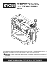
... the operator's manual before using
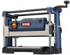
this product. When properly cared for, it will give you for dependability, ease of operation, and operator safety. PORTABLE PLANER
AP1301
Your portable planer has been engineered and manufactured to our high standard for your purchase.
English Manual - Page 2
... proof of purchase and return all defects in workmanship or materials in your RYOBI® power tool for a period of two years from the date of Terms...9 � Features...10-11...from which includes the date of purchase (for making it was purchased. The replacement power tool will repair any faulty workmanship, and either request service under state law, including warranties of...
English Manual - Page 3
... switch is damaged should wear safety glasses and be properly repaired or replaced by removing starter keys.
DON'T FORCE TOOL. Serious injury could ignite fumes.
3 Never yank cord to operate tool.
DON'T OVERREACH. Learn the tool's applications and limitations as well as the specific potential hazards related to contain long hair.
...
English Manual - Page 5
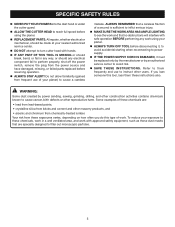
...PARTS. ALWAYS REMEMBER that no obstructions will interfere with hands.
IF ANY PART OF THIS TOOL IS MISSING or should break, bend, or fail in a well ventilated area, and work with ..., remove the plug from frequent use to filter out microscopic particles.
5 If you do this tool, loan them frequently and use of your planer) to cause cancer, birth defects or other masonry...
English Manual - Page 6
...
6 Precautions that involve your hands away from the blade will allow you to operate the tool better and safer. No Hands Symbol
Failure to keep your safety. Hot Surface
To reduce ...injury or damage, avoid contact with side shields, or a full face shield when operating this tool.
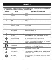
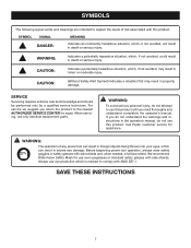
Please study them and learn their meaning. Proper interpretation of the following symbols may be ...
English Manual - Page 7
... care and knowledge and should be performed only by a qualified service technician.
Before beginning power tool operation, always wear safety goggles or safety glasses with this product. CAUTION:
(Without Safety Alert...The following signal words and meanings are intended to explain the levels of any power tool can result in foreign objects being thrown into your eyes, which can result in...
English Manual - Page 8
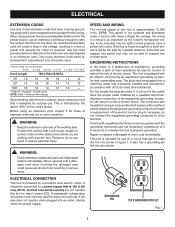
...by Underwriter's Laboratories (UL) should be able to reduce the risk of this tool on lumber, tools or other obstructions while you are working with all local codes and ordinances. This...without yellow stripes is intended for a greater distance. Do not modify the plug provided. This tool is the equipment-grounding conductor. NOTE: AWG = American Wire Gauge
When working with a ...
English Manual - Page 9
... Sawing Any cutting operation where the blade extends completely through or partial cut by the workpiece being dropped into the tool first.
Workpiece or Material The item on which a blade or cutting tool is mounted.
A push stick (not a push block) should be or has been cut . Revolutions Per Minute (r/min.) The number...
English Manual - Page 10
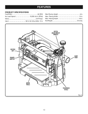
Planing Depth 1/8 in . DEPTH ADJUSTMENT
HANDLE
SWITCH KEY
POWER SWITCH
DUST PORT
WORK TABLE
10
THICKNESS SCALE
Fig. 2 Max. Planing Width 13 in . FEATURES
PRODUCT SPECIFICATIONS
Feed Rate 26 FPM No Load Speed 10,000 r/min. (RPM) Motor 2 HP Peak Input 120 V, AC Only, 60Hz, 15 A
Max Planing Height 6 in.
Max. Net Weight 53.5 lbs.
English Manual - Page 11
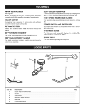
.... 1 2 3 4 5 6
Fig. 3
Description
Qty.
CUTTER HEAD ASSEMBLY
The cutter head assembly controls the depth of 6 in .
Depth Adjustment Handle ...1
Screw ...1
Switch Key...1
Magnetic Blade Wrench ...1
Hex Key ...1
Open-end Wrench ...1
11 Before attempting to use your workpiece. AUTOMATIC FEED
Infeed and outfeed rollers feed the wood through the planer. WORK TABLE
The ...
English Manual - Page 13
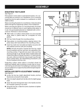
...When mounting the planer to . INSTALLING DEPTH ADJUSTMENT HANDLE
See Figure 5.
Locate the hex key, depth adjustment handle, and hex head screw among the loose parts.
Place the depth ... sure bolts are long enough to go through holes in the shaft.
Using the hex key, rotate the screw clockwise to a workbench or other stable surface. If the planer is recommended you...
English Manual - Page 15

...cupped or bowed down to turn the switch OFF ( O ) and remove the key. WARNING:
Always remove the switch key when the tool is not properly supported.
Simply turn ON ( l ). Feeding against keeping the ...the workpiece over and plane it can jam the planer.
SWITCH KEY
Fig. 6
15 WARPED WOOD
Little or no damage to the tool has occurred before planing to keep it in a
secure location...
English Manual - Page 17
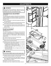
...both blades to offset such planing imperfections. Unplug the planer and remove the switch key. Lower the cutter head assembly. Remove the two thumb screws holding...notched end of the finished workpiece. ADJUSTMENTS
WARNING:
Before performing any adjustment, make sure the tool is most easily accomplished
from the power supply. BLADE ADJUSTMENT
See Figures 10 - 11. ...
English Manual - Page 18
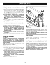
... prevent accidental starting that could cause possible serious personal injury, turn off the tool, remove the switch key, and unplug the planer before performing any other parts may produce ridges on ...place or the planer will engage when the head is equipped with side shields during power tool operation or when blowing dust.
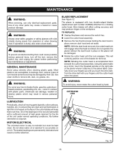
of oil wiped on the workpiece. MAINTENANCE
WARNING:
When ...
English Manual - Page 19
... easier access when removing the rear brush cap.
Unplug planer and remove the switch key.
Using a flat-head screwdriver, unscrew the brush cap. Periodic cleaning and waxing is...brush assembly is in . Never replace one side without replacing the other debris can cause the tool to secure.
NOTE: Blades should be clean to use a mild, nonflammable tar and pitch ...
English Manual - Page 22
... provided below.
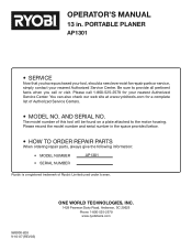
• HOW TO ORDER REPAIR PARTS
When ordering repair parts, always give the following information:
• MODEL NUMBER
AP1301
• SERIAL NUMBER
Ryobi® is a registered trademark of this tool will be found on a plate attached to provide all pertinent facts when you have purchased your nearest Authorized Service Center.
Repair Sheet - Page 3
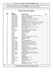
...(M6 X P1 X 60 mm SOC. May Be Purchased Locally 3
HANDLE ASSEMBLY (INC. Always mention the model number in . KEY NOS. 26-28 1 HOOD DOOR 1 HURRICANE KNOB 2 * SCREW (M5 X P0.8 X 10 mm PAN HD 4 * ... PLANER or when ordering repair parts. PLANER - MODEL NUMBER AP1301
The model number will be found on a plate attached to the motor housing. KEY NOS. 2-6 AND 91 1 HANDLE KNOB ASSEMBLY 1 HANDLE ...
Repair Sheet - Page 4
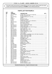
...SCALE LENGTH 1
LOGO LABEL 1 MOTOR/SWITCH ASSEMBLY (INC. SPINDLE 1
BASE 1 L.H. MODEL NUMBER AP1301
The model number will be found on a plate attached to the motor housing. LEFT 2
RETAINER...SPROCKET 2
* WASHER (Ø4 X Ø15 X 2t 2 * SCREW (M4 X P0.7 X 12 mm HEX SOC. KEY NOS. 66 AND 95) ......... 1
SMALL COVER (LEFT SIDE 1 LARGE COVER (LEFT SIDE 1 SPRING COIL - RIGHT 2
BEARING...
Repair Sheet - Page 6
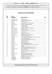
...regarding your PLANER or when ordering repair parts. MODEL NUMBER AP1301
The model number will be found on a plate attached to the motor housing.
PLANER -
KEY NO. 22 1 BRUSH HOLDER 2 BRUSH AND SPRING ...1 BALL BEARING (6201LLB 2 ARMATURE ASSEMBLY (INC. May Be Purchased Locally 6 Always mention the model number in . KEY NO.
1 2 3 4 5 6 7 8 9 10 11 12 13 14 15 16 17 18 19 20...
Repair Sheet - Page 7
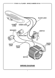
MODEL NUMBER AP1301
POWER GREEN LEAD CORD BRUSHES
WHITE LEAD
WHITE LEAD
WHITE LEAD
BLACK LEAD
SWITCH
WHITE LEAD
MOTOR
WIRING DIAGRAM
7 RYOBI 13 in. PLANER -
Similar Questions

Machine Is Not Turning On When Inserting Key And Pushing Up Key Pops Out?
(Posted by estherflam 2 years ago)

P716 Goes To Strobe (ing).
After little time as flashlight unit goes to strobing and no return to flashlight use.How to control...
After little time as flashlight unit goes to strobing and no return to flashlight use.How to control...
(Posted by Shipwreckedinmontauk 2 years ago)

I Need A Rotor For The Motor
a part of my motor portable planer
a part of my motor portable planer
(Posted by Jbgelectronica 6 years ago)

Sharpening Ryobi Planer Knives
What is the proper sharpening angle for Ryobi AP1301 planer knives?
What is the proper sharpening angle for Ryobi AP1301 planer knives?
(Posted by midgiesdan2 12 years ago)