
Installation Instructions
Page 3
... room 7 Installation cavity 7 Furniture/fixtures 7 Base 7 Connecting the power 8 Additional grounding procedure 8 Grounding instruction 8 Connecting the water 8 Installation dimensions 9 Single installation 9 SideĆbyĆSide installation 10 Water connection 11 Appliance dimensions 12 1. 18" Appliance (Freezer/Freezer with Ice and Water dispenser 12 2. 18" Appliance (Wine unit 13 3. 24" Appliance (Refrigerator...
... room 7 Installation cavity 7 Furniture/fixtures 7 Base 7 Connecting the power 8 Additional grounding procedure 8 Grounding instruction 8 Connecting the water 8 Installation dimensions 9 Single installation 9 SideĆbyĆSide installation 10 Water connection 11 Appliance dimensions 12 1. 18" Appliance (Freezer/Freezer with Ice and Water dispenser 12 2. 18" Appliance (Wine unit 13 3. 24" Appliance (Refrigerator...
Installation Instructions
Page 6
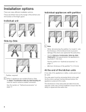
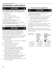
... SideĆby ĆSide Sealing kit must be connected firmly to prevent damage if the doors are opened at the same time. - i Note - When dimensioning the partition for model 4, note the thickness of the furniture fronts to the wall, the floor and overhead furniture/fixtures before the appliance is visible... square and the exact size. 6 The side panel must be used to ensure a stable connection. See the section on Optional accessories" on page 17. 3. 4. The dimensions of the partition 5/8" (16 mm).
... SideĆby ĆSide Sealing kit must be connected firmly to prevent damage if the doors are opened at the same time. - i Note - When dimensioning the partition for model 4, note the thickness of the furniture fronts to the wall, the floor and overhead furniture/fixtures before the appliance is visible... square and the exact size. 6 The side panel must be used to ensure a stable connection. See the section on Optional accessories" on page 17. 3. 4. The dimensions of the partition 5/8" (16 mm).
Installation Instructions
Page 7
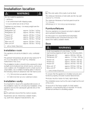
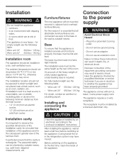
... properly, the base must be installed in rooms which are connected securely to adjacent and overhead furniture/fixtures. If installation next to observe the specified dimensions of the installation cavity for a troubleĆfree installation of the appliance and for empty weight see the following table: Refrigerator 24" Refrigerator 30" approx...
... properly, the base must be installed in rooms which are connected securely to adjacent and overhead furniture/fixtures. If installation next to observe the specified dimensions of the installation cavity for a troubleĆfree installation of the appliance and for empty weight see the following table: Refrigerator 24" Refrigerator 30" approx...
Installation Instructions
Page 8
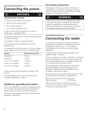
... Refrigerator24" Refrigerator 30" Freezer 18" (incl. The shutĆoff valve for the pipe. For the permitted installation areas and dimensions see "Installation dimensions", page 8. Plug into a grounded 3 prong outlet. - Do not use an adapter. - The appliance comes with local plumbing... regulations. Some local regulations may result in death, fire, or electrical shock. Maximum outer diameter of the receptacle see Installation dimensions", page 8. IceMaker) Freezer 30" (incl. For the installation position of the water pipe (without fittings): 13/32" (10...
... Refrigerator24" Refrigerator 30" Freezer 18" (incl. The shutĆoff valve for the pipe. For the permitted installation areas and dimensions see "Installation dimensions", page 8. Plug into a grounded 3 prong outlet. - Do not use an adapter. - The appliance comes with local plumbing... regulations. Some local regulations may result in death, fire, or electrical shock. Maximum outer diameter of the receptacle see Installation dimensions", page 8. IceMaker) Freezer 30" (incl. For the installation position of the water pipe (without fittings): 13/32" (10...

Installation Instructions
Page 10
SideĆbyĆSide installation The cavity dimensions indicated above for the respective appliance apply to a SideĆbyĆSide installation of the cavity widths indicated for installation of the power connection ...
SideĆbyĆSide installation The cavity dimensions indicated above for the respective appliance apply to a SideĆbyĆSide installation of the cavity widths indicated for installation of the power connection ...

Installation Instructions
Page 12
For further information about the different styles check the DESIGN GUIDE. Appliance dimensions7. 1. 18" Appliance (Freezer/Freezer with Ice and Water dispenser) e) e) Front view (without door panel) Legend: a) Adjustment in levelling legs +13/8" (35 mm) / -1/2" (13 mm). d) This dimension may vary depending on installation, panel thickness and kitchen hardware. 12 e) Unit dimensions Note: One design of door panel may vary. b) Dimensions may vary. c) Thickness of the wooden panel displayed.
For further information about the different styles check the DESIGN GUIDE. Appliance dimensions7. 1. 18" Appliance (Freezer/Freezer with Ice and Water dispenser) e) e) Front view (without door panel) Legend: a) Adjustment in levelling legs +13/8" (35 mm) / -1/2" (13 mm). d) This dimension may vary depending on installation, panel thickness and kitchen hardware. 12 e) Unit dimensions Note: One design of door panel may vary. b) Dimensions may vary. c) Thickness of the wooden panel displayed.

Installation Instructions
Page 13
d) This dimension may vary. e) Unit dimensions Note: One design of door panel may vary. For further information about the different styles check the DESIGN GUIDE. 13 c) Thickness of the wooden panel displayed. b) Dimensions may vary depending on installation, panel thickness and kitchen hardware. 2. 18" Appliance (Wine unit) e) e) Front view (without door panel) Legend: a) Adjustment in levelling legs +13/8" (35 mm) / -1/2" (13 mm).
d) This dimension may vary. e) Unit dimensions Note: One design of door panel may vary. For further information about the different styles check the DESIGN GUIDE. 13 c) Thickness of the wooden panel displayed. b) Dimensions may vary depending on installation, panel thickness and kitchen hardware. 2. 18" Appliance (Wine unit) e) e) Front view (without door panel) Legend: a) Adjustment in levelling legs +13/8" (35 mm) / -1/2" (13 mm).

Installation Instructions
Page 14
3. 24" Appliance (Refrigerator/Freezer/Freezer with Ice and Water dispenser) e) e) Front view (without door panel) Legend: a) Adjustment in levelling legs +13/8" (35 mm) / -1/2" (13 mm). d) This dimension may vary. e) Unit dimensions 14 Note: One design of door panel may vary. For further information about the different styles check the DESIGN GUIDE. b) Dimensions may vary depending on installation, panel thickness and kitchen hardware. c) Thickness of the wooden panel displayed.
3. 24" Appliance (Refrigerator/Freezer/Freezer with Ice and Water dispenser) e) e) Front view (without door panel) Legend: a) Adjustment in levelling legs +13/8" (35 mm) / -1/2" (13 mm). d) This dimension may vary. e) Unit dimensions 14 Note: One design of door panel may vary. For further information about the different styles check the DESIGN GUIDE. b) Dimensions may vary depending on installation, panel thickness and kitchen hardware. c) Thickness of the wooden panel displayed.

Installation Instructions
Page 15
b) Dimensions may vary. 4. 24" Appliance (Wine unit) e) e) Front view (without door panel) Legend: a) Adjustment in levelling legs +13/8" (35 mm) / -1/2" (13 mm). c) Thickness of the wooden panel displayed. d) This dimension may vary depending on installation, panel thickness and kitchen hardware. For further information about the different styles check the DESIGN GUIDE. 15 e) Unit dimensions Note: One design of door panel may vary.
b) Dimensions may vary. 4. 24" Appliance (Wine unit) e) e) Front view (without door panel) Legend: a) Adjustment in levelling legs +13/8" (35 mm) / -1/2" (13 mm). c) Thickness of the wooden panel displayed. d) This dimension may vary depending on installation, panel thickness and kitchen hardware. For further information about the different styles check the DESIGN GUIDE. 15 e) Unit dimensions Note: One design of door panel may vary.

Installation Instructions
Page 16
c) Thickness of the wooden panel displayed. e) Unit dimensions 16 Note: One design of door panel may vary depending on installation, panel thickness and kitchen hardware. d) This dimension may vary. For further information about the different styles check the DESIGN GUIDE. b) Dimensions may vary. 5. 30" Appliance (Refrigerator/Freezer/Freezer with Ice and Water dispenser) e) e) Front view (without door panel) Legend: a) Adjustment in levelling legs +13/8" (35 mm) / -1/2" (13 mm).
c) Thickness of the wooden panel displayed. e) Unit dimensions 16 Note: One design of door panel may vary depending on installation, panel thickness and kitchen hardware. d) This dimension may vary. For further information about the different styles check the DESIGN GUIDE. b) Dimensions may vary. 5. 30" Appliance (Refrigerator/Freezer/Freezer with Ice and Water dispenser) e) e) Front view (without door panel) Legend: a) Adjustment in levelling legs +13/8" (35 mm) / -1/2" (13 mm).
Installation Instructions
Page 18
...Ćfree installation. Before starting the installation, check that the installation cavity complies with ice maker - q Check the dimensions of the adjacent furniture/fixtures. Follow the instructions in the section on Installation dimensions" on page 8. Freezer units with the installation requirements. All furniture parts in the section on Connecting the water" on...
...Ćfree installation. Before starting the installation, check that the installation cavity complies with ice maker - q Check the dimensions of the adjacent furniture/fixtures. Follow the instructions in the section on Installation dimensions" on page 8. Freezer units with the installation requirements. All furniture parts in the section on Connecting the water" on...

Installation Instructions
Page 22
...! q Change the attachment plates crosswise. 22 (609,6-647,7) q If the installation cavity is equal to the section on Installation dimensions" starting on the rear panel of the antiĆtip brackets and therefore the appliance, another method must be used to fasten the...262;tip brackets securely. If the supplied fastening screws do not permit secure attachment of the cavity. IMPORTANT NOTE ! Specify the detailed dimensions according to the width of the antiĆtip brackets: - i Important information for various applications. Select the fastening screws according to ...
...! q Change the attachment plates crosswise. 22 (609,6-647,7) q If the installation cavity is equal to the section on Installation dimensions" starting on the rear panel of the antiĆtip brackets and therefore the appliance, another method must be used to fasten the...262;tip brackets securely. If the supplied fastening screws do not permit secure attachment of the cavity. IMPORTANT NOTE ! Specify the detailed dimensions according to the width of the antiĆtip brackets: - i Important information for various applications. Select the fastening screws according to ...

Installation Instructions
Page 24
... near the rear panel of the cavity. 8. q Attach the wooden beam to the connecting pipe when pushing in the beam. Always observe the indicated gap dimensions to prevent damage to the rear panel of the cavity and mark drill holes in the appliance. If possible, always screw the wooden beam to...
... near the rear panel of the cavity. 8. q Attach the wooden beam to the connecting pipe when pushing in the beam. Always observe the indicated gap dimensions to prevent damage to the rear panel of the cavity and mark drill holes in the appliance. If possible, always screw the wooden beam to...

Installation Instructions
Page 27
... the front. d CAUTION d Never use a cordless screwdriver! q Screw the attachment plate lugs (top) to the appliance base and is very important to point 6 of this dimension for height adjustment. The heightĆadjustable feet at the front and rear can all the way towards the wooden beam. 13. If using a wooden... gage for the subsequent alignment of the cavity q Unscrew the heightĆadjustable feet until the mark on the base has reached the indicated guide dimension (1¼" / 32 mm).
... the front. d CAUTION d Never use a cordless screwdriver! q Screw the attachment plate lugs (top) to the appliance base and is very important to point 6 of this dimension for height adjustment. The heightĆadjustable feet at the front and rear can all the way towards the wooden beam. 13. If using a wooden... gage for the subsequent alignment of the cavity q Unscrew the heightĆadjustable feet until the mark on the base has reached the indicated guide dimension (1¼" / 32 mm).

Installation Instructions
Page 36
Shorten the finger guard ! q Insert the finger guard into the gap between the appliance and adjacent furniture (1.). q Transfer the door dimensions to the required length. 36 i The recesses on the width and the design of the door. IMPORTANT NOTE ! If doors exceed the standard height, use ...
Shorten the finger guard ! q Insert the finger guard into the gap between the appliance and adjacent furniture (1.). q Transfer the door dimensions to the required length. 36 i The recesses on the width and the design of the door. IMPORTANT NOTE ! If doors exceed the standard height, use ...
Use & Care Manual
Page 6
... 18" 300 lbs / 135 kg Wine unit 24" 350 lbs / 160 kg Installation room The appliance should not be mounted securely to observe the specified dimensions of the installation cavity for a troubleĆfree installation of the appliance and for the first time, clean the inside of frost. In particular ensure...
... 18" 300 lbs / 135 kg Wine unit 24" 350 lbs / 160 kg Installation room The appliance should not be mounted securely to observe the specified dimensions of the installation cavity for a troubleĆfree installation of the appliance and for the first time, clean the inside of frost. In particular ensure...